RESISTANCE
(REFER
TO
UNIT LABEL
llIGH.PRESSURE
CONNECTION TO
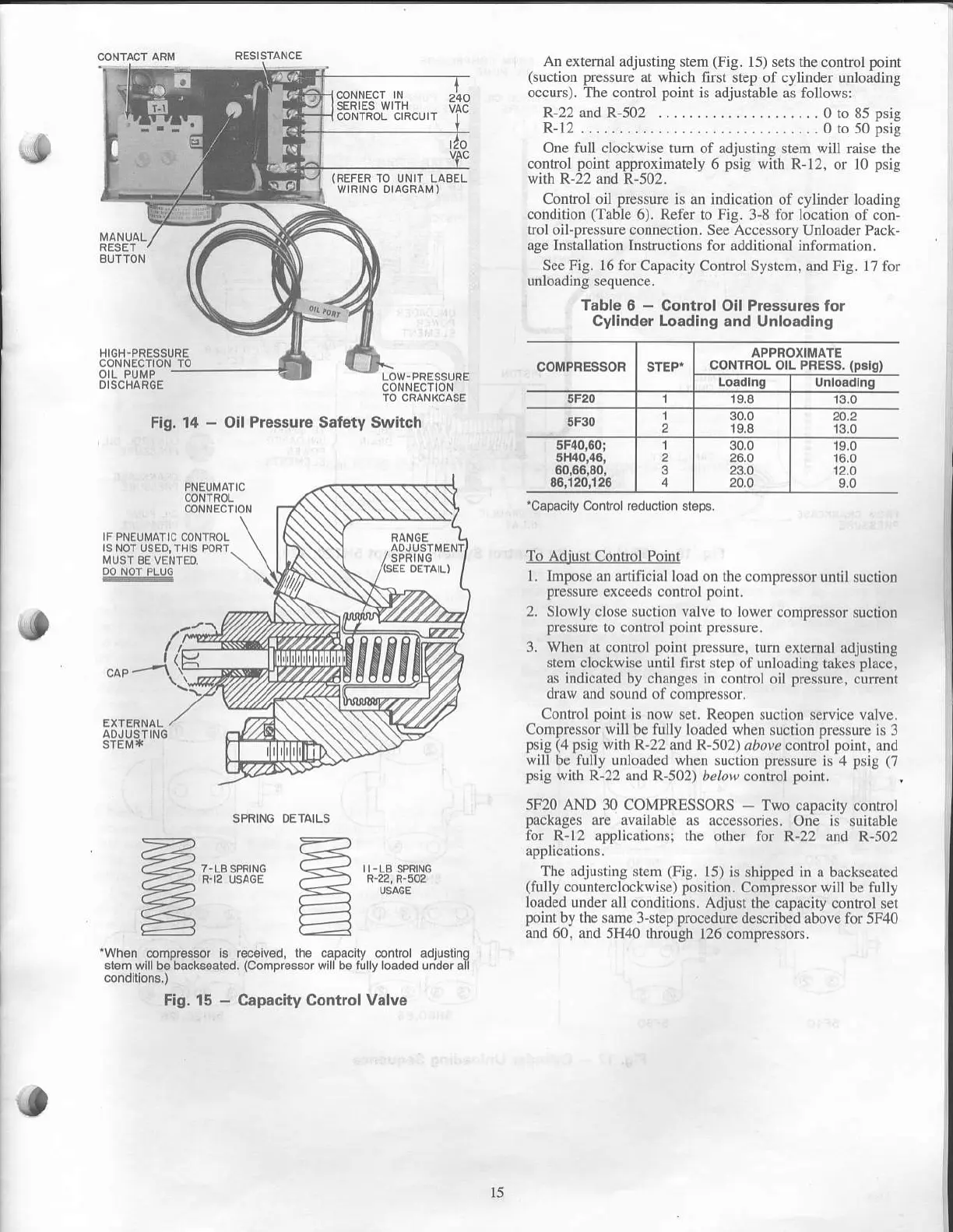
Fig. 14
-
Oll Pre$ure Safety Switch
CONTROL
CONNECTION
An extemal
adjusting stem
(Fig.
15) s€ts the control
point
Guction
Fessure
at
which
first step of cylinder unloading
occurt. The control
point
is adjustable
as follows:
R-22 and R-502 . . . . . . . . .
.
.
. . . . . . . . . . 0 to 85 Dsis
R-12 ................
.... .........0 ro s0
bsig
One full clockwise
tum of adjusting stem will raise the
contlol
point
approximately
6
psig
with
R-12, or 10
psig
with R-22 and
R-502.
Control oil
pressure
is an indication of cylinder loading
condition
(Table
6). Refer to Fig.
3-8 for location of con-
trol oil-pressurc connection. See Accessory Unloader Pack-
age Inslallation Insfiuctions
for additional information.
See.Fig.
16 for
Capacity Control System, and Fig. 17 for
umoaorng sequence.
Table 6
-
Control Oil Prossuros tor
Cylinder Loading
.nd Unloadlng
COMPRESSORSTEP"
APPFOXIIIiIATE
CONTFOL OIL PFESS.
(p!lg)
Loadlng Unlo.dln
5F20 1 19.8
5F30
1
2
30,0
19.8
20.2
13,0
5F40,60;
5H40,{1,
60,0€,80,
86,120,126
1
2
3
30.0
24,0
23.0
20.0
r6.0
12,0
9.0
toapaclly
Control reducllon.l6pE.
FPNEUMATIC
@NIFO!
tS NOT USEDI TI]IS FOFT
MUST
8E VENIEO
To Adjust Conhol Point
l. Impose an anificial load on the compressot
until suction
pressure
exceeds control
point.
2.
Slowly close suction
valve
io lower compressor
suction
pressurc
ro contml
Pornt Pressure.
3. When at control
poin! pressure,
tum extemal adjusting
stem clockwbe until fint step of unloading
takes
place,
as indicated
by,changes in control oil
pressure.
current
oraw ano souno ol
compressor.
Control
Doint
is now
set. ReoDen suction service valve,
Compresso;
will
be fully loaded
;hen
sucrion
pressure
is 3
psig
(4
psig
with
R-22 and R-502r arrvc
con$ol
poinr.
and
will be fully unloaded when
suction
pressure
is 4
psig
(7
psig
$ith
R-22 and R-502) ,?loa
conEol
poinl.
5F20 AND 30 COMPRESSORS
-
Two capacity conrrol
packages
are available
as accessories. One is
suitable
for_R-12 applicationsi the
other for R-22 and R-502
The adjusting stem
(Fig.
15)
is shipped in a backseated
(fully
countercloclwise)
positjon.
Compressor will be
fully
loaded under all condirions.
Adjusl the capacity control ser
poinl
by lhe same 3-step
procedule
described above lor 5F,()
and 60.
and 5H4O through 126 compressors.
SPRINO
OETAILS
ft',r** ffi'mi*
'When
comDrcssor is r€c€iv€d.
lhe caDaciv
conllol adiustino
sl6m lvlll b6 backs6at6d.
(Compr€ssor
wlli b6
'irlly
load€d
Jniln all
Fig. 15
-
Cap.city Control
V.lve
15
 Loading...

