1.
Turn
pump
shaft ro
align
drive
trng with slor in end of
crankshrft.
Holding pump rssembly wilh thumbs on the
? screws, slidc rssenbly into bearing head until tang
engages slot. A slight
rotation should !lign screws witb
tapped
holes in adaplcr. Start screws ro hold allgnment
and then installbaiance ofscrewsand
lock washeN. Torque
all screws
(/r
20) to 8
l0 ft lb.
Srrrt
conrpressor rnd check oil
pressure.
This oil
pump
opcrxtes in eilher direction of rotation. The conect oil
pressure
for compressors
using this punrp is
.15
b 55
psrg above sucoon
prcssurc.
OIL
PRESSURE RECULATING VALVE
(nonadjustable.
Fig. 27) is located on the side of compressor
.djacent
to
seal housing. Regulator
maintains corrcct
oi1
prcssrre
(Table
6)
and
ensures
srtisfrctory unkradcr opcrrtion.
I
,r
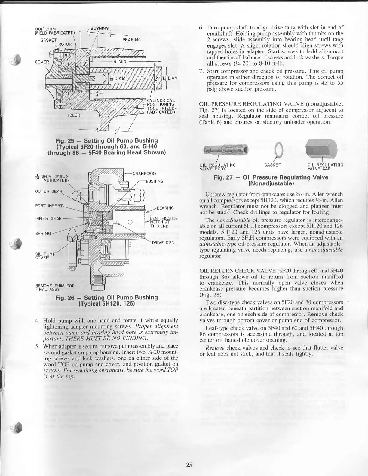
FIJ[,1.;.1
Fig,25
-
Setting Oil
Pump Bushing
(Typical
5F20
through 60, and
5H40
through 86
-
5F40 Bearing
Head Shownl
Fig.27
-
Oil Pressure
Regulating Valve
{Nonadiustable}
Unscrew
regulalor liom crnnkcasei use
516
in.
Allen
wrench
on nllcomprcssors except 5Hll0,
which rcquires 7r nr. Allen
wrench. Regulator
nrust not bc ckrggcd r d
plunger
must
not
be
stuck.
Check
drillings to reguhtor li)r fbulnrg.
The t.o,ta.rfuttubla oil
pres$rre regulator is interchange-
able or allcunent 5F,H
c(nnpressors except 5H l20 rnd 126
nmdels. 5H120 rnd 126 unirs hLtlc larger. nonadjustrble
regulat(ns. E rly 5F.H compresson
werc equipped with
an
a./prl.r/te type oil'pressure
reguhtor. When rn rdjust ble-
type
regul.ting v lve needs replrcing, use a ll.)/rar./irrralrl?
regurrcr.
OIL RBTURN CHECK
vALVE
(5Fl0
rhmugh
60,
aod 5H1o
rhrough
86) rUows oil to return Uonr suction m niibld
ro
cLllrkcnse. This nomrally open vrlve closes
wheD
crankcase
pressure becomcs highcr than strclion
ptdssure
(Fig.28).
Two disc-iype check valves on 5F20 and 30 conrpressors
are locared
bcnealh partirion bctwecn suclion Dranilbld and
crnrkcase. one on each side of compressor. Renrove check
valves through bottom covef
or pump
end of comprcssor.
Lealtype check
vnlve on
5F,10
rnd
60 and 5H40
through
86 conrpressors is
.tc.essiblc
thLough, and
located aI lop
cenrer
01, hrnd'hole cover opening.
,qenr!" check valves and check to see that tluter valve
or leaf does no! stick. and that it seats tighdy.
f,
-
"t
5.
Fig.25
-
Setting
Oil Pump
Bushing
(Tvpical
5H120,
126)
Hold
pump
with one hanJ
ano rorrrc ir
q\iL
{qJ:rll}
Iightening
adapter rn.Jnling
\crcq
'.
P/,,/r
r
,r/rEanlrl
beNeen
punp
and beatinq
head
boft is uitrcmel) ttn'
portant.
THERE
MUST BE No
BINDING.
When
adapter is
secure, renlole
pump
assembly and
place
.e.ond
ga'ker
on
pump hou.rn8. hr.efl
r$
.
20 l ounl-
ins scress and lock
udshers.
one
o| ci'hfr
.i.l(
or Ine
worJ
TOP on
punp
end cnve
. dnd
po'irion
lJ.Ler
orl
scress. For reiat nin
s
ope\t
ttur\ bc u'cttu"n
ToP
25
 Loading...

