!
Clean strainer with solv€nt or replace if broken
or cor-
rcded. When replacing suciion slrainer, do not damage
it.
On 5H120 and 126 compresson.
posilioned
manifold cover
plate
must
compr€ss strainer bail.
If bail is
too short,
grasp
on sides and elongate it enough to be compressed
by man-
ifold
cover. Position bail between the 2 bosses on inside
of
manifold cover
ro
prevenr
"rrainer ftnm
ru-ni'rg.
Cylinder
Head and Valve Assemblies
CYLINDER
IIEAD TNSPECTION
-
Remove cylindcr heads
aDd
check
heads for
warping,
cracks
.Lnd
danrage 1()
g.Nkel
VALVE
INSPECTION
(Fig.
32)
Disassemblv
-
Remove cylinderhead. Loosen cap screws
holding
discharge valve seal to dischrrge
valve guide.
nd
cnp
screws holding valve
guide
1() vrlvc
plate.
ReNove cap
screws
holding valve
plate
to cylinder block. Renove vulve
plate
from
cylinder block and discharge valve
guide
frcnr
Inspection
-
Inspect
suction and
dischxrgc valve
discs rnd
valve
seats
for cracks or excessive
wear
(T.6le
ll).
Check
cylildeFsleeve
valve
stops for Lrncvcn
wcdr.
ReDrace vnrves
if cracked
or wom. If valve seats are worn, reptace
com,
plete
valve
plate
assembly. If cylindeFsleeve valve slops
arc wom,
replace sleeve.
Renss€mblv
-
Pistons
mrst be
below tops
(J1
cylinder sleeves
To
posilion
corecdy,
tum
crankshaft or lbrce pistons
down
l Place
suction valve springs in vnlve
plate
recesses.
Large
spring
coil should be in full coniaci wirh botom
of
2.
Place suction
valve disc on valve springst
press
disc into
valve plate
recess. Slide
valve
retainer clips into
placc
rFig
JJ).
Clip\
musr nor \.ver
\r \r
lfie-.pring,
or
pins.
Valve relainer clips 5F20-2061
(5F
compressors)
and
5H40-2061
(5H
compressors) are iield supplied.
Bolt
valve plate
to cylinder block. Remove vaive clips.
Place
discharge valve
springs in discharge
valve guide
Place
discharge valve disc over springs, and fit inner
spring
in
place
over
valve
disc. Hand-tighten bolts hold
ing
inner seat to valve
guide (valve
guide
assembly).
Place
valve
guide
assembly on
valve ptate.
Tighten all
bolts
and bend tabs on lock
'rasher
and lock plates.
Re-
place
cylinder head.
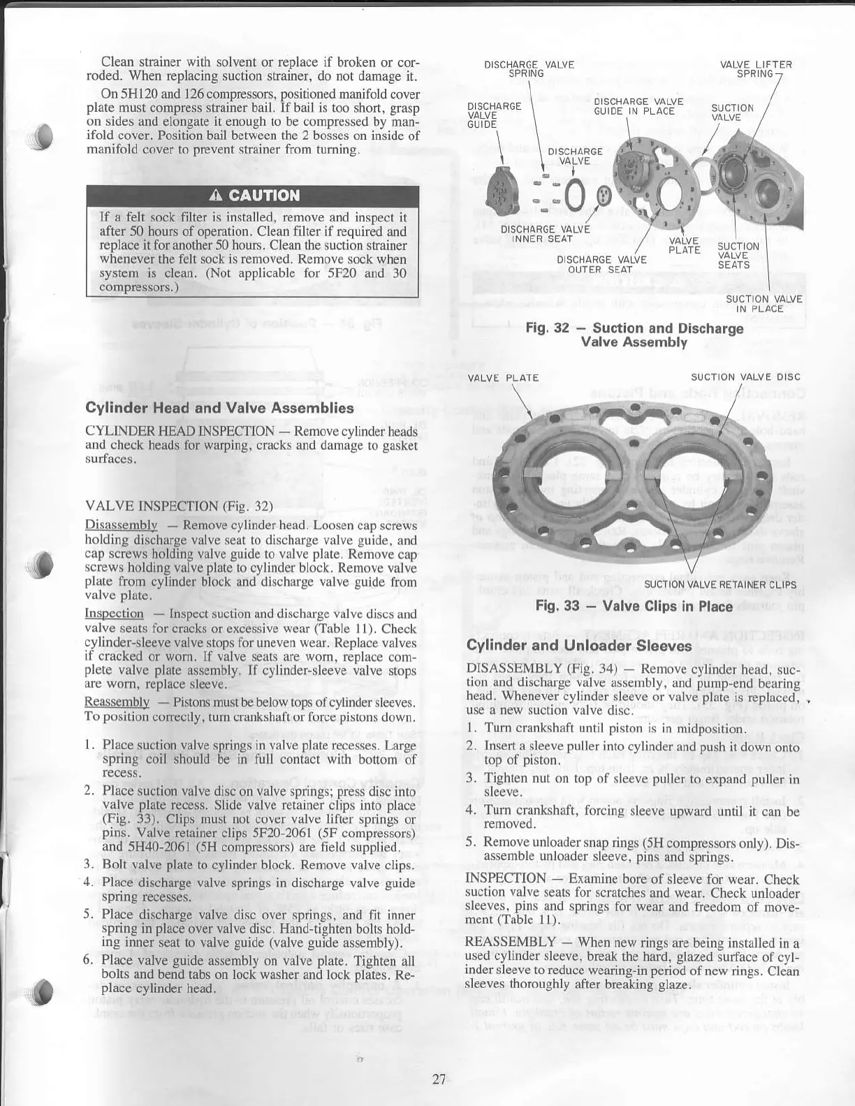
SUCTION VALVE
IN PLACE
Fig.32
-
Suction
and Discharge
Valve Assembly
SUCTION
VALVE RETAINfR CLIPS
Fig. 33
-
Vslve
Clips in Pl6ce
Cylinder
and Unloader
Sleeves
DISASSEMBLY
(Fig.
34)
Rcmove cylnrder
nc!o, suc-
rion rnJ Ji\h:rrye \
lve.6,ernbly. :'Id purrp
{nJ
hel
nE
hc
d
wh(neve
Lylir-Jer.lee\e.r vrl\c
thie
i.,epl.ie.r.
l Turn crankshril
until
pisron
is in lllidposirion.
2. lnse.t.a deeve puller
into cylindcr
and
push
ir down
onto
I TiShren 1ur
.n r"l ot.lee\e
p
'lcr
ro exDand
pul[r
in
4.
Turn crankshaft, lorcing
sleeve upward
until it can be
5. R(rri\c.rnloJder
.ndp
ring. r5H
comp'.
'..,r.,,
1) I
Dr.-
assenrbic dnlorder
sleeve,
pins
and springs.
INSPECTION
Examine bore
of sleeve fbf weaL.
Check
suction
valve seats for
scratches and wear.
Check unloader
sleeves, pins
and springs for
wear and freedom
of move,
ment
(Table
I l).
REASSEMBLY
-
When new
rinss are beins instrlled
in a
used cylinder sleeve.
break rbe haid, glazed;urface
of cyt,
inder
sleeve to reduce
wearing-in
period
ofnew rings. Clean
sleeves
thoroughly aft€r
breaking
glaze.
t
3.
5.
6.
If
a felt sock filter
js jnstalled.
remove and inspect
il
after
50 hours ofoperation. Clean filter
jf
required and
replace it
for another 50
hours.
Clean
the suction
strainer
whenever the felt sock is removed. Remove sock when
system is clean.
(Not
applicable tbr 5F20 and
30
21
 Loading...

