(ToP)
/
l-,"i1
o211
-
r"
,.I/LJ'J
;_*
!
UNLOADEF CYLINDER
COVER PLATE
LINE
I
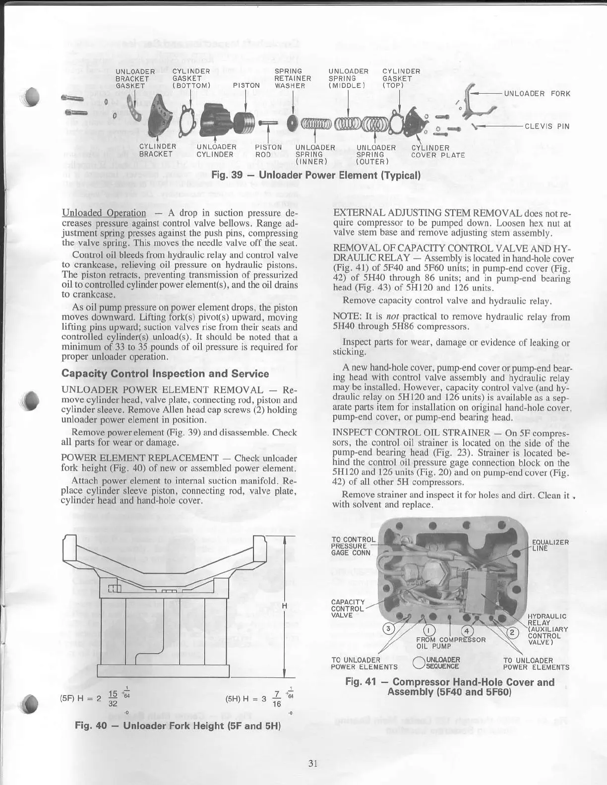
Fig.41
-
Compressor Hand-Hole
Cover ano
Assembly
{5F40
and 5F60)
E
"t&d#rj,ry,@
Unloaded
Ooeration
-
A drop in suclion
pressurc
dc
creases pressure
against cont'ol
valve
bellows. Range ad-
u'tmcIr
'tring
pre.-e. Ji'.,in.n thL
p.r.h
tir
.
..r
,t!e\,
.!
the valve
spring. This move! lhe needle
valvc
oli lhc seat.
Conrrol
oil bleed$
fron hydrarilic rclay and control valve
to
crankcase, relieving oil
pressurc
on hydr.ulic
pislons.
The pislon
retracts,
preventing
tranrmission of
prcssrrized
oil tocontrolled
cylinder
powef element(s),
Lrnd the oildrains
As oil
pump pfessurc
on
powerclenrenl
drcps.
the
piston
lnoles
downward. Lifling fbrk(s)
pivol(t
upwrrd, moving
liliinS pins
upwrrdi suction
vrlves rise
li(n
therr scats lnd
cortrolled
cylinde(s)
unbrd(s). lr shorld
be noted thrr Ll
minimum
of 33 to 35
pounds
o{ oil
pressulc
is rcquired tlr
lrope.
unloader operation.
Capacity
Control
Inspection and
Sewice
UNLOADER
POWER
ELEMEN'|
REMOVAL
-
Rc-
nrove
cylinder
head,
valve
plrtc,
conn.cring rod, pist(nr
nd
cylinder
sleeve.
Remove
Allen hcrd crp scLcws
(2)
holding
unloader power
elenlent in
position.
Rcmove powerelemenl
(Fig.
39) rnd dis$scnrblc. Check
all parts
for wear
or damagc.
POWER
ELEMENT REPLACEMENT
-
Check unlo.rdcr
lork
height
(Fig.
40)
of trcw or rsscmblcd power
elenleot.
Attach
power
clenrent
to intemal sucli{rr
Nrniiold. Re-
placc
cylinder sleeve
piston,
connecting rod, valvc
pldtc,
cylinder
head and hand-hole cover.
(sFJH =2
=.!'
(5H)
r-l
L]NLOADER
P STON UNLOADER
CYLINDER FOD SPR ING
lINNER)
Fig.
39
-
Unloader Power Element
(Typical)
TO UNLOADER
/-\
UNLOADEi
POWERELEMENTS
\-/SEOUENCE
EXTERNAL ADJUSTINC
STEM REMOVAL
docs not rc
qurfe
col]rpresyr'to bc punped
down. Looscn hex
nur ar
vllve
ltem base and removc rdiustiflg
ltem asscnrbly.
REMOVAI-
OFCAPACITY CONTROL VALVE
AND HY-
DRAULIC RELAY
Assenrbly is locrted nr hand-holc
co!el
(Fig.,ll)
ol 5F10 rnd 5F60
unitsi in
pumt
end
cover
(Fig.
42) of 5H,10 through 86 un$:
rnd in
pu
ip cnd
berring
head
(Fis.
43)
ol 5Hl20 a cl 126 unils.
Remove
crtacity control
vrlvc
lnd hydnrLrlic
rrhy.
NOTE|
lt is ,r/
plLrcticrl
ro renrovc
hyd ulic
rclir! lionr
5H40
thfough 5H86 cornprcssors.
Inspect
pti(s
lbr wcrr, dun ge
or cvidcncc of le
king ol
sticking.
A new hrndlxne
cover,
prn p-cnd
covcr
orpunrp-cnd berF
ing
herd
with
control vrhe rsscmbly
lnd fiydruulic
rchy
niay
be
inst,rlled.
However, crpaciry
connr)l llll!c
(rnd
hy-
dfttulic tehy on
5HI20 nd 126 units) is rvrillrble
irs r sep-
rMtc
parls
ite litr instrllrlion
on ofiginrl hnnd-lx)le
cover.
punrp'cnd
cover. or puDrp cnd
bcrring hcxd.
INSPECTCONTROL
OIL STRA]NER
On
5F conrpres-
soLs, the
conlfol oil stftriner is locatcd
on rhc sidc
ol rhe
punrp'cnd
be ing
head
(Fig.
l3). Srrriner
is loclred
be
hind the conLrcl oil prcssurc grge
connecli(D
trbck on lhc
5H l20
rnd 1 26 units
(Fig.
?0) dnd on pu
rp-cnd covcf
(trig.
,l:)
()1
rll
olhcr 5H conrpressols.
Remove slrrircr dnd inspect
it lirr holcs
rnd did. Cle,rn ir
,
wilh solveDl
and replace.
Fig.40
-
Unloader Fork Height
(5F
and
5H)
3l
 Loading...

