62-12023 2-2
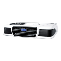
Figure 2.1 Main Unit Components
2.3 Condensing Section
The condenser section (see
Figure 2.2
) contains the condenser fan and coil, receiver/drier, oil separator,
condenser pressure control valve, condenser pressure control switch,
hot gas valve, high pressure switch and
microprocessor. On road/standby units the condenser also houses the standby compressor, control box and
rectifier/transformer assembly. In addition, single phase units are fitted with a start box which contains the capacitors
and relay.
2.3.1 Condenser Coil
The condenser is of the microchannel type and acts as a heat exchanger in which the compressed refrigerant gas
is condensed into a liquid and lowered in temperature. Air movement over the condenser is provided by a fan
mounted in the condensing section.
2.3.2 Hot Gas Solenoid Valve (HGS1)
HGS1 is normally closed and prevents discharge gas from entering the evaporator. The valve opens to allow hot
gas refrigerant to be delivered from the compressor to the evaporator during heat or defrost modes.
&RQGHQVHU
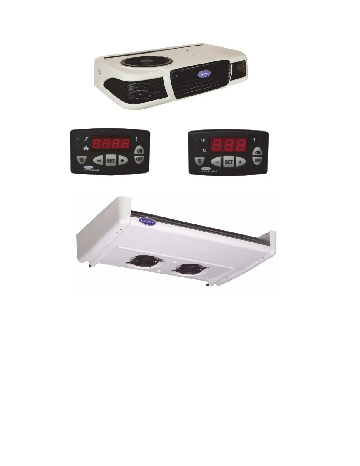
&DE&RPPDQG7ZR
&DE&RPPDQG
(YDSRUDWRU
 Loading...

