4-1 62-12023
SECTION 4
Temperature Control
4.1 Sequence Of Operation
General operation sequences for cooling, null, and heating are provided in the following paragraphs. The micropro-
cessor automatically selects the mode necessary to maintain box temperature at setpoint.
4.1.1 Cooling Mode
a. With return air temperature above setpoint and decreasing, the unit will be cooling with the compressor and
evaporator fans operating. (See Section 2.8.1 for a description of the refrigeration circuit during cooling.)
The condenser fan will operate under the control of the condenser pressure control switch (HP2). The green
unit operating LED will operate in accordance with Figure 3.2. If discharge pressure rises to HP2 setting
(See Section 2.6.2), the condenser fan motor (CFM) will turn on for a minimum of three minutes.
b. If discharge temperature increases to the setpoint of the quench thermostat (BPT), the thermostat will close,
energizing the quench valve (BPV). This will allow liquid into the suction line in order to cool the compressor.
Once the discharge temperature decreases to the setpoint of the BPT, the thermostat will open, DE-energiz-
ing the BPV.
c. Once temperature decreases to the setpoint the unit will enter the null mode. If the continuous air flow
parameter is set to ON, the evaporator fans will continue to operate with all other components OFF. If the
continuous air flow parameter is OFF, the evaporator fans and all other components will be OFF. A five min-
ute delay is required before restart is allowed.
d. If temperature increases during the null mode, the unit will restart in cooling.
4.1.2 Heating Mode
If temperature continues to decrease the unit will enter the heating mode with the compressor and evaporator fans
operating, the hot gas solenoid valve (HGS1) energized (open), the condenser pressure control valve (HGS2)
energized (closed) and the quench valve (BPV) energized (open). If discharge pressure rises to the HP2 setting
(See Section 2.6.2) HGS2 will de-energize (open) and BPV will de-energize (closed) for a minimum of one minute.
If discharge pressure remains the same or rises the condenser fan motor (CFM) will turn on. (See Section 2.8.2 for
a description of the refrigeration circuit during heat and defrost.)
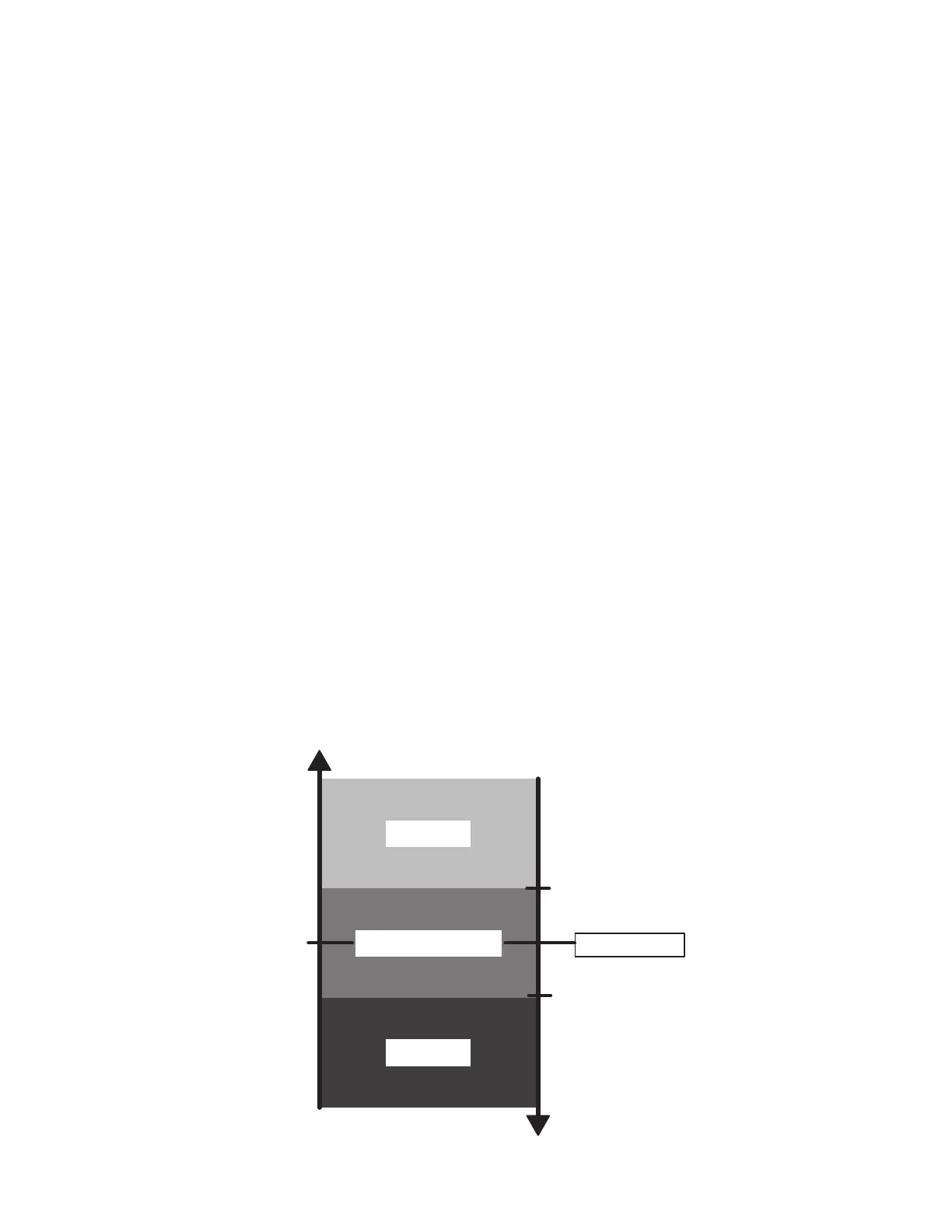
Figure 4.1 Operating Sequence - Perishable Mode
+5.4°F (+3°C)
or +3.6°F (+2°C)
or +1.8°F (+1°C)
-1.8°F (-1°C)
or -3.6°F (-2°C)
or -5.4°F (-3°C)
(setting)
SETPOINT
COOL
UNIT STOPPED
HEAT
 Loading...

