must use Table 12 (21,000 Btuh/Burner). See input listed on
rating plate.
a. Obtain average yearly gas heat value (at installed altitude)
from local gas supplier.
b. Obtain average yearly gas specific gravity from local gas
supplier.
c. Find installation altitude in Table 11 or 12.
d. Find closest natural gas heat value and specific gravity in
Table 11 or 12.
e. Follow heat value and specific gravity lines to point of
intersection to find orifice size and manifold pressure
settings for proper operation.
f. Check and verify burner orifice size in furnace. NEVER
ASSUME ORIFICE SIZE. ALWAYS CHECK AND
VERIFY.
g. Replace orifice with correct size if required by Table 11 or
12. Use only factory-supplied orifices. See EXAMPLE 2.
EXAMPLE 2: (0–2000 ft altitude)
For 22,000 Btuh per burner application use Table 11.
Heating value = 1000 Btu/cu ft
Specific gravity = 0.62
Therefore: Orifice No. 43*
Manifold pressure: 3.7-in. wc
*Furnace is shipped with No. 43 orifices. In this example
all main burner orifices are the correct size and do not need
to be changed to obtain proper input rate.
3. Adjust manifold pressure to obtain correct input rate.
a. Turn gas valve ON/OFF switch to OFF.
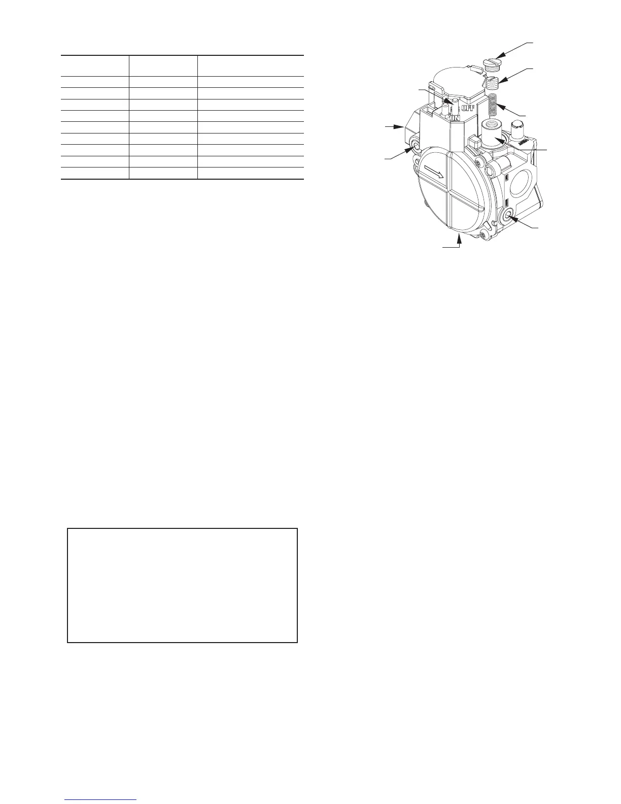
b. Remove manifold pressure tap plug from gas valve. (See
Fig. 52.)
c. Connect a water column manometer or similar device to
manifold pressure tap.
d. Turn gas valve ON/OFF switch to ON.
e. Manually close blower door switch.
f. Set thermostat to call for heat.
g. Remove regulator seal cap and turn regulator adjusting
screw counterclockwise (out) to decrease input rate of
clockwise (in) to increase input rate.
h. Install regulator seal cap.
i. Leave manometer or similar device connected and proceed
to Step 4.
NOTE: DO NOT set manifold pressure less than 3.2-in wc or
more than 3.8-in. wc for natural gas at sea level. If manifold
pressure is outside this range, change main burner orifices or refer
Table 11 or 12.
NOTE: If orifice hole appears damaged or it is suspected to have
been redrilled, check orifice hole with a numbered drill bit of
correct size. Never redrill an orifice. A burr-free and squarely
aligned orifice hole is essential for proper flame characteristics.
4. Verify natural gas input rate by clocking meter.
NOTE: Gas valve regulator adjustment cap must be in place for
proper input to be clocked.
a. Turn off all other gas appliances and pilots served by the
meter.
b. Run furnace for 3 minutes in heating operation.
c. Measure time (in sec) for gas meter to complete 1 revolu-
tion and note reading. The 2 or 5 cubic feet dial provides a
more accurate measurement of gas flow.
d. Refer to Table 10 for cubic ft of gas per hr.
e. Multiply gas rate (cu ft/hr) by heating value (Btu/cu ft) to
obtain input.
If clocked rate does not match required input from Step 1, increase
manifold pressure to increase input or decrease manifold pressure
to decrease input. Repeat steps b through e until correct input is
achieved. Reinstall regulator seal cap on gas valve.
5. Set temperature rise.
The furnace must operate within the temperature rise ranges
specified on the furnace rating plate. Do not exceed tempera-
ture rise range specified on unit rating plate. Determine the
temperature rise as follows:
NOTE: Blower access door must be installed when taking tem-
perature rise reading. Leaving blower access door off will result in
incorrect temperature measurements.
Table 8–Altitude Derate Multipler for U.S.A.
ALTITUDE
(FT)
PERCENT
OF DERATE
DERATE MULTIPLIER
FACTOR*
0–2000 0 1.00
2001–3000 8–12 0.90
3001–4000 12–16 0.86
4001–5000 16–20 0.82
5001–6000 20–24 0.78
6001–7000 24–28 0.74
7001–8000 28–32 0.70
8001–9000 32–36 0.66
9001–10,000 36–40 0.62
* Derate multiplier factors are based on midpoint altitude for altitude range.
EXAMPLE 1:
88,000 BTUH INPUT FURNACE INSTALLED AT 4300 FT.
Derate Furnace Input Rate
Furnace Input Rate X Multiplier = at Installation
at Sea Level Factor Altitude
88,000 X 0.90 = 79,200
Fig. 52—Gas Control Valve
A04166
REGULATOR
SEAL CAP
REGULATOR
ADJUSTMENT
SCREW
REGULATOR SPRING
GAS PRESSURE
REGULATOR
ADJUSTMENT
MANIFOLD
PRESSURE TAP
INLET
PRESSURE TAP
ON/OFF SWITCH
1/2˝ NPT INLET
1/2˝ NPT OUTLET
35
 Loading...