EasyManua.ls Logo

Carrier 17EX User Manual

Carrier 17EX
120 pages
To Next Page IconTo Next Page
Page #1 background imageLoading...
Page #1 background image
Start-Up, Operation, and Maintenance Instructions
SAFETY CONSIDERATIONS
Centrifugal liquid chillers are designed to provide safe
and reliable service when operated within design speci-
fications. When operating this equipment, use good judg-
ment and safety precautions to avoid damage to equip-
ment and property or injury to personnel.
Be sure you understand and follow the procedures and
safety precautions contained in the chiller instructions
as well as those listed in this guide.
DO NOT VENT refrigerant relief valves within a building. Outlet
from rupture disc or relief valve must be vented outdoors in ac-
cordance with the latest edition of ASHRAE (American Society of
Heating, Refrigeration, and Air Conditioning Engineers) 15. The
accumulation of refrigerant in an enclosed space can displace oxy-
gen and cause asphyxiation.
PROVIDE adequate ventilation in accordance with ASHRAE 15,
especially for enclosed and low overhead spaces. Inhalation of high
concentrations of vapor is harmful and may cause heart irregulari-
ties, unconsciousness, or death. Misuse can be fatal. Vapor is heavier
than air and reduces the amount of oxygen available for breathing.
Product causes eye and skin irritation. Decomposition products are
hazardous.
DO NOT USE OXYGEN to purge lines or to pressurize a chiller
for any purpose. Oxygen gas reacts violently with oil, grease, and
other common substances.
NEVER EXCEED specified test pressures, VERIFY the allowable
test pressure by checking the instruction literature and the design
pressures on the equipment nameplate.
DO NOT USE air for leak testing. Use only refrigerant or dry
nitrogen.
DO NOT VALVE OFF any safety device.
BE SURE that all pressure relief devices are properly installed and
functioning before operating any machine.
DO NOT WELD OR FLAME CUT any refrigerant line or vessel
until all refrigerant (liquid and vapor) has been removed from chiller.
Traces of vapor should be displaced with dry air or nitrogen and
the work area should be well ventilated. Refrigerant in contact with
an open flame produces toxic gases.
DO NOT USE eyebolts or eyebolt holes to rig chiller sections or
the entire assembly.
DO NOT work on high-voltage equipment unless you are a quali-
fied electrician.
DO NOT WORK ON electrical components, including control pan-
els, switches, starters, or oil heater until you are sure ALL POWER
IS OFF and no residual voltage can leak from capacitors or solid-
state components.
LOCK OPENANDTAG electrical circuits during servicing. IF WORK
IS INTERRUPTED, confirm that all circuits are deenergized be-
fore resuming work.
AVOID SPILLING liquid refrigerant on skin or getting it into the
eyes. USE SAFETY GOGGLES. Wash any spills from the skin
with soap and water. If any enters the eyes, IMMEDIATELY FLUSH
EYES with water and consult a physician.
NEVER APPLY an open flame or live steam to a refrigerant cyl-
inder. Dangerous overpressure can result. When necessary to heat
refrigerant, use only warm (110 F [43 C]) water.
DO NOT REUSE disposable (nonreturnable) cylinders or
attempt to refill them. It is DANGEROUS AND ILLEGAL. When
cylinder is emptied, evacuate remaining gas pressure, loosen
the collar and unscrew and discard the valve stem. DO NOT
INCINERATE.
CHECK THE REFRIGERANT TYPE before adding refrigerant to
the chiller. The introduction of the wrong refrigerant can cause dam-
age or malfunction to this chiller.
Operation of this equipment with refrigerants other than those
cited herein should comply with ASHRAE-15 (latest edition). Con-
tact Carrier for further information on use of this chiller with other
refrigerants.
DO NOTATTEMPT TO REMOVE fittings, covers, etc., while chiller
is under pressure or while chiller is running. Be sure pressure is at
0 psig (0 kPa) before breaking any refrigerant connection.
CAREFULLY INSPECT all relief devices, rupture discs, and other
relief devices AT LEAST ONCE A YEAR. If chiller operates in a
corrosive atmosphere, inspect the devices at more frequent
intervals.
DO NOT ATTEMPT TO REPAIR OR RECONDITION any relief
device when corrosion or build-up of foreign material (rust, dirt,
scale, etc.) is found within the valve body or mechanism. Replace
the device.
DO NOT install relief devices in series or backwards.
USE CARE when working near or in line with a compressed spring.
Sudden release of the spring can cause it and objects in its path to
act as projectiles.
RUN WATER PUMPS when removing, transferring, or charg-
ing refrigerant.
DO NOT STEP on refrigerant lines. Broken lines can whip about
and cause personal injury.
DO NOT climb over a chiller. Use platform, catwalk, or staging.
Follow safe practices when using ladders.
USE MECHANICAL EQUIPMENT (crane, hoist, etc.) to lift or
move inspection covers or other heavy components. Even if com-
ponents are light, use such equipment when there is a risk of slip-
ping or losing your balance.
BE AWARE that certain automatic start arrangements CAN EN-
GAGE THE STARTER. Open the disconnect ahead of the starter
in addition to shutting off the machine or pump.
USE only repair or replacement parts that meet the code require-
ments of the original equipment.
DO NOTVENTOR DRAIN waterboxes containing industrial brines,
liquid, gases, or semisolids without permission of your process con-
trol group.
DO NOT LOOSEN waterbox cover bolts until the waterbox has
been completely drained.
DOUBLE-CHECK that coupling nut wrenches, dial indicators, or
other items have been removed before rotating any shafts.
DO NOT LOOSEN a packing gland nut before checking that the
nut has a positive thread engagement.
PERIODICALLY INSPECT all valves, fittings, and piping for cor-
rosion, rust, leaks, or damage.
PROVIDE A DRAIN connection in the vent line near each pres-
sure relief device to prevent a build-up of condensate or rain
water.
17EX
Externally Geared Centrifugal Liquid Chillers
50/60 Hz
1500 to 2250 Nominal Tons (5280 to 7910 kW)
Manufacturer reserves the right to discontinue, or change at any time, specifications or designs without notice and without incurring obligations.
Book 2
Tab 5d
PC 211 Catalog No. 531-721 Printed in U.S.A. Form 17EX-1SS Pg 1 7-97 Replaces: New

Table of Contents

Question and Answer IconNeed help?

Do you have a question about the Carrier 17EX and is the answer not in the manual?

Carrier 17EX Specifications

General IconGeneral
BrandCarrier
Model17EX
CategoryChiller
LanguageEnglish

Summary

SAFETY CONSIDERATIONS

17EX CHILLER FAMILIARIZATION

System Components

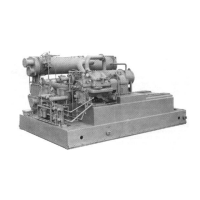
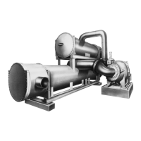
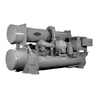
Lists main components like heat exchangers, compressor, motor.

Cooler

Vessel where refrigerant evaporates to cool water.

Condenser

Vessel where refrigerant condenses, releasing heat to water.

Compressor

Component that circulates refrigerant and maintains pressure.

REFRIGERATION CYCLE

LUBRICATION CYCLE

Compressor Lubrication Cycle

Detailed description of compressor oil circulation and filtration.

External Gear Lubrication Cycle

Detailed description of external gear oil circulation and filtration.

STARTERS

CONTROLS

Definitions

Explains Analog Signal, Digital Signal, and Volatile Memory.

General

Overview of the microprocessor-based control center.

LID Operation and Menus

GENERAL

Describes LID display behavior and configuration options.

ALARMS AND ALERTS

Explains alarm and alert indications and actions.

LID DEFAULT SCREEN MENU ITEMS

Overview of status, schedule, setpoint, and service menus.

MENU STRUCTURE

Explains how to navigate through the LID menu system.

TO VIEW OR CHANGE POINT STATUS

Steps to view actual values of control points and sensors.

SERVICE OPERATION

TO VIEW AND CHANGE SET POINTS

Table 2 — LID Display Data

EXAMPLE 1 — STATUS01 DISPLAY SCREEN

Table 2 — LID Display Data (cont)

EXAMPLE 2 — STATUS02 DISPLAY SCREEN

Shows status data for relays, contacts, and optional inputs.

EXAMPLE 3 — STATUS03 DISPLAY SCREEN

Displays status for options boards, sensors, and spare inputs.

Table 2 — LID Display Data (cont)

EXAMPLE 4 — STATUS04 DISPLAY SCREEN

Shows status for oil pumps and gear oil temperature.

EXAMPLE 5 — SETPOINT DISPLAY SCREEN

Displays and allows modification of set points.

Table 2 — LID Display Data (cont)

EXAMPLE 6 — CONFIGURATION (CONFIG) DISPLAY SCREEN

Allows configuration of chiller settings and options.

Table 2 — LID Display Data (cont)

EXAMPLE 7 — LEAD/LAG CONFIGURATION DISPLAY SCREEN

Configuration for lead/lag chiller operation.

Table 2 — LID Display Data (cont)

EXAMPLE 8 — SERVICE1 DISPLAY SCREEN

Accesses service parameters for overrides and settings.

Table 2 — LID Display Data (cont)

EXAMPLE 9 — SERVICE2 DISPLAY SCREEN

Configures optional inputs and 20mA power sources.

EXAMPLE 10 — SERVICE3 DISPLAY SCREEN

Configures proportional bands and guide vane travel.

Table 2 — LID Display Data (cont)

EXAMPLE 11 — MAINTENANCE (MAINT01) DISPLAY SCREEN

Displays capacity control algorithm status and parameters.

EXAMPLE 12 — MAINTENANCE (MAINT02) DISPLAY SCREEN

Shows override and alert status for various components.

PIC System Functions

CAPACITY CONTROL

How the PIC modulates guide vanes for capacity.

DEADBAND

Tolerance for chilled water temp control point.

OCCUPANCY SCHEDULE

How schedules determine chiller operation periods.

Safety Controls

Ramp Loading Control

Capacity Override (See Table 4)

High Discharge Temperature Control

Auto. Restart After Power Failure

Surge Prevention Algorithm

Lead/Lag Control

LEAD/LAG OPERATION

Standby Chiller Configuration and Operation

Ice Build Control

Attach to Network Device Control

Service Operation

TO ACCESS THE SERVICE SCREENS

START-UP/SHUTDOWN/RECYCLE SEQUENCE (Fig. 22)

Local Start-Up

Procedure for initiating chiller start-up locally.

Shutdown Sequence

Chilled Water Recycle Mode

BEFORE INITIAL START-UP

Job Data Required

List of essential documentation for start-up.

Equipment Required

Tools and instruments needed for initial setup.

Remove Shipping Packaging

MOTOR

Instructions for removing motor shipping braces and tags.

MOTOR

Motor Electrical Connection

Guidelines for connecting motor wiring and grounding.

Leak Test the Chiller

Chiller Dehydration

Inspect Wiring

CHECK INSULATION RESISTANCE

Procedure to measure stator winding insulation resistance.

Motor Pre-Start Checks

External Gear Pre-Start Checks

Check Starter

MECHANICAL STARTERS

Checks and procedures for mechanical starters.

SOLID-STATE STARTERS

Precautions for solid-state starters.

Set Up Chiller Control Configuration

Input the Design Set Points

Steps to modify chiller operating set points.

Input Service Configurations

Procedures for setting service parameters like password, time.

INPUT EQUIPMENT SERVICE PARAMETERS IF NECESSARY

Configure SERVICE1 Table

Modifying service parameters in the SERVICE1 table.

Modify Minimum and Maximum Load Points (T1/P1; T2/P2) If Necessary

PERFORM AN AUTOMATED CONTROL TEST

INITIAL START-UP

Preparation

Pre-start checks before initiating chiller startup.

Starting the Chiller

Check Motor Rotation

INITIAL MOTOR START-UP

Procedure for initial motor rotation check.

Initial Coupled Start-Up

Disc Coupling Installation and Alignment

Check Oil Pressure and Compressor Stop

Calibrate Motor Current Demand Setting

To Prevent Accidental Start-Up

Hot Alignment Check

Check Chiller Operating Condition

Instruct the Operator

OPERATING INSTRUCTIONS

Operator Duties

Responsibilities of the chiller operator.

PUMPOUT AND REFRIGERANT TRANSFER PROCEDURES

Preparation

Steps before performing pumpout or refrigerant transfer.

Operating the Optional Pumpout Compressor

Transferring Refrigerant into the Economizer/Storage Vessel

Transferring Refrigerant into the Cooler/Condenser/Compressor Section

Return Chiller to Normal Operating Conditions

GENERAL MAINTENANCE

Adding Refrigerant

Procedures for adding refrigerant to the chiller.

Removing Refrigerant

Steps for transferring refrigerant to another vessel.

Adjusting the Refrigerant Charge

How to adjust refrigerant charge for performance.

Refrigerant Leak Testing

Methods for testing refrigerant leaks.

Test After Service, Repair, or Major Leak

Procedure for leak testing after service.

Repair the Leak, Retest, and Apply Standing Vacuum Test

Contact Seal Maintenance (Refer to Fig. 36)

SEAL DISASSEMBLY (Fig. 36)

Step-by-step instructions for seal disassembly.

SEAL REASSEMBLY (Fig. 36)

Chiller Alignment

ALIGNMENT METHODS

Overview of alignment techniques, dial indicator preferred.

General

General alignment principles and tolerances.

High Speed Coupling Alignment

Alignment procedure for high-speed couplings.

Low Speed Coupling Alignment

Alignment procedure for low-speed couplings.

PRELIMINARY ALIGNMENT

Steps for initial rough alignment.

NEAR FINAL ALIGNMENT

Steps for near-final alignment within dial indicator range.

NEAR FINAL ALIGNMENT (continued)

Parallel in elevation

Alignment adjustment using shims in the elevation plane.

Angular in plan

Alignment adjustment in the plan plane.

Parallel in plan

Final parallel alignment adjustment in the plan plane.

Correcting Angular Misalignment

Preparation

Measuring shaft angular misalignment.

Measurement

Compensating for runout in alignment readings.

Adjustment

Correcting Parallel Misalignment

FINAL ALIGNMENT

HOT ALIGNMENT CHECK

General

Performing alignment check after components reach operating temperature.

Disassembled Couplings

Alignment check steps when couplings are disassembled.

Assembled Couplings

Alignment check steps with couplings assembled.

DOWELING

Techniques

Procedures for doweling compressor, gear, and drive to sole plates.

SCHEDULED MAINTENANCE

Service Ontime

Resetting the SERVICE ON TIME value for tracking.

Inspect the Control Center

Maintenance for the control center cabinet.

Check Safety and Operating Controls Monthly

Performing automated control tests monthly.

Changing the Oil Filters

COMPRESSOR OIL FILTER

Procedure for changing the compressor oil filter.

EXTERNAL GEAR OIL FILTER

Oil Changes

COMPRESSOR OIL

Procedure for draining and refilling compressor oil.

EXTERNAL GEAR OIL

Procedure for draining and refilling external gear oil.

Inspect Relief Valves and Piping (Scheduled Maintenance)

Motor Maintenance

SLEEVE BEARINGS (Motor Maintenance)

Oil Changing

Procedures for draining and refilling motor bearing oil reservoirs.

Reassembly (Bearing)

Motor Handling/Rigging

Motor Storage

External Gear Storage

EXTENDED DOWNTIME

Compressor Bearing Maintenance

External Gear Maintenance

Daily

Daily checks for external gear.

Weekly

Weekly checks for external gear.

Monthly

Monthly checks for external gear.

Semi-Annually

Semi-annual checks for external gear.

Inspect the Heat Exchanger Tubes

COOLER

Inspection and cleaning of cooler tubes.

CONDENSER

Inspection and cleaning of condenser tubes.

Water Leaks

Inspect the Starting Equipment

Check Pressure Transducers

Pumpout System Maintenance

OPTIONAL PUMPOUT COMPRESSOR OIL CHARGE

Procedure for adding oil to the pumpout compressor.

TROUBLESHOOTING GUIDE

Overview

Introduction to the PIC's troubleshooting features and LID display.

Checking the Display Messages

Checking Temperature Sensors

RESISTANCE CHECK

Steps to check sensor resistance.

VOLTAGE DROP

Steps to check sensor voltage drop.

Checking Pressure Transducers

Control Algorithms Checkout Procedure

MAINT01 Capacity Control

Status of capacity control algorithm.

MAINT02 Override Status

Status of override values.

MAINT03 Surge/HGBP Status

Status of surge and HGBP control.

MAINT04 LEAD/LAG Status

Status of lead/lag operation.

OCCDEFM Time Schedules Status

Status of occupied schedules.

Control Test

A. SHUTDOWN WITH ON/OFF/RESET-OFF

B. TIMING OUT OR TIMED OUT

C. IN RECYCLE SHUTDOWN

D. PRE-START ALERTS

E. NORMAL OR AUTO.-RESTART

F. SPARE SENSOR ALERT MESSAGES

L. CHILLER PROTECT LIMIT FAULTS

L. CHILLER PROTECT LIMIT FAULTS (cont)

M. CHILLER ALERTS

N. OTHER PROBLEMS/MALFUNCTIONS

Control Modules

RED LEDs

Explains the meaning of red LEDs on PSIO and 4-in/2-out modules.

GREEN LEDs

Explains the meaning of green LEDs for communication status.

Notes on Module Operation

Details on module communication and operation.

Processor/Sensor Input/Output Module (PSIO) (Fig. 52)

INPUTS

Describes PSIO module inputs and their usage.

OUTPUTS

Describes PSIO module outputs and their usage.

Starter Management Module (SMM) (Fig. 53)

INPUTS

Describes SMM module inputs and their usage.

OUTPUTS

Describes SMM module outputs and their usage.

Replacing Defective Processor Modules

INSTALLATION OF NEW PSIO MODULE

PHYSICAL DATA AND WIRING SCHEMATICS

Tabulation — Impeller Clearances (Open-Drive Compressors)

NOTES FOR FIG. 60

I GENERAL

General notes for starter and wiring installation.

II POWER WIRING TO STARTER

Notes on power wiring requirements for the starter.

III CONTROL WIRING

Notes on control wiring requirements and best practices.

Related product manuals