8
Connect Ground and Power Wir
es
Connect ground wire to ground connection in control box for
safety. Connect power wiring to contactor as shown in Fig. 9.
DISCONNECT
PER N. E. C. AND/OR
LOCAL CODES
CONTACTOR
GROUND
LUG
FIELD GROUND
WIRING
FIELD POWER
WIRING
A91056
Fig. 9 --- Line Connections
Connect Control W
iring
Route 24v control wires through control wiring grommet and
connect leads to control wiring. See Thermostat Installation
Instructions for wiring specific unit combinations.
Use No. 18 AWG color--coded, insulated (35°C minimum) wire.
If thermostat is located more than 100 ft from unit, as measured
along the control voltage wires, use No. 16 AWG color--coded,
insulated wire to avoid excessive voltage drop.
All wiring m u st b e NE C C lass 1 and mu st b e separated fro m
incoming power leads.
Use furn ace transfo rm er, fan coil transform er, or accessory
transformer for control power, 24v/40va minimum.
NOTE: Use of available 24v accessories may exceed the
minimum 40va power requirement. Determine total transformer
loading and increase the transformer capacity or split the load
with an accessory transformer as required.
Final Wiring
Check
IMPORTANT: Check factory wiring and field wire connections
to ensure terminations are secured properly. Check wire routing
to ensure wires are not in contact with tubing, sheet metal, etc.
STEP 9 —CompressorCrankcaseHeater
When equipped with a crankcase heater, furnish power to heater a
minimum of 24 hr before starting unit. To furnish power to heater
only, set therm ostat to OFF an d close electrical d iscon n ect to
outdoor unit.
A crankcase heater is required if refrigerant tubing is longer than
80 ft. Refer to the Long Line Guideline--Residential Split--System
Air Conditioners and Heat Pumps.
STEP 10 —Install Electrical Accessories
Refer to the individual installation instructions packaged with kits
or accessories when installing.
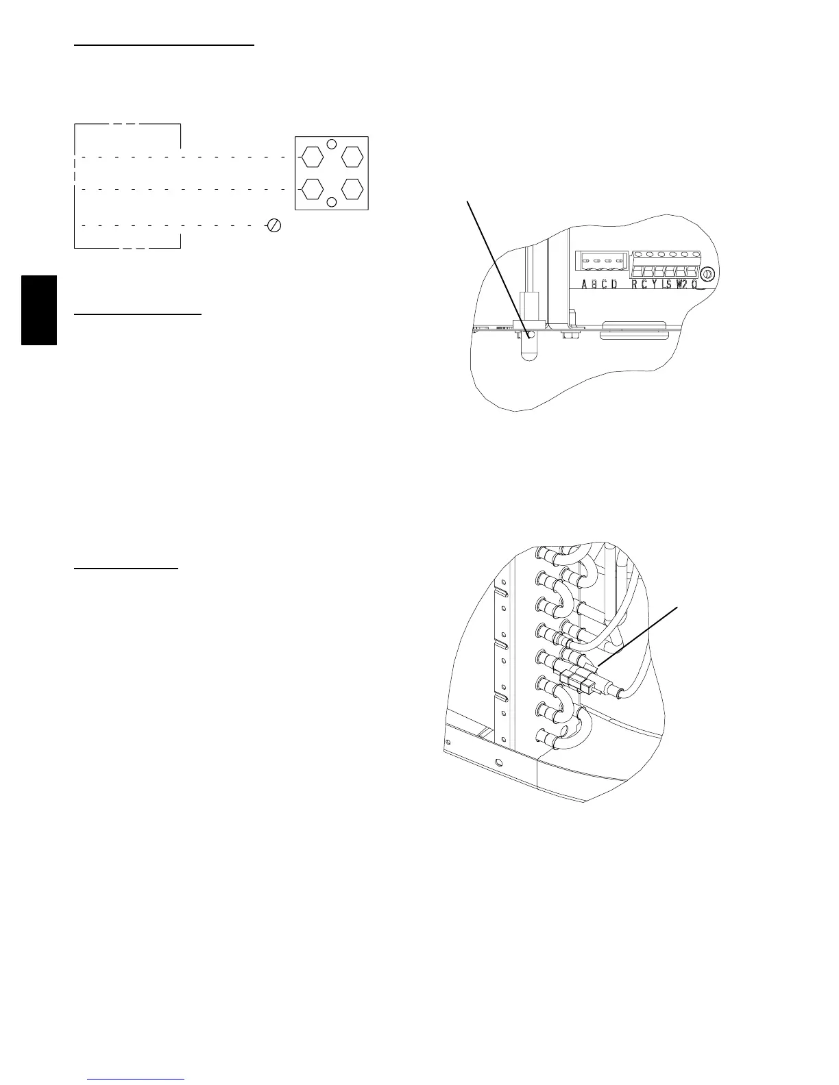
STEP 11 —Check OAT Thermistor and OCT Thermistor
Attachments
Outdoor Air Temperature (OAT) Thermistor is factory installed
by inserting the nibs on either sides of the thermistor body
through a keyhole in the bottom shelf of the control box and
locking it in place by turning it 90 degrees, such that the spherical
end of a nib faces the front of the control box.
Check to make sure the OAT is locked in place. See Fig. 10.
OAT Thermistor must be locked in
place with spherical nib end facing
towards the front of the control box
A05408
Fig. 10 --- Outdoor Air Thermistor (OAT) Attachment
The Outdoor Coil Temperature (OCT) Thermistor is factory
installed on the 3/8” diameter stub tube located on the coil
assembly.
Check to make sure that it is securely attached with the clip as
shown in Fig. 11.
OCT Thermistor
must be secured
tight on stub tube.
A05409
Fig. 11 --- Outdoor Coil Thermistor (OCT) Attachment
25HPA

 Loading...


