5
STEP 7 —Make Piping Connections
!
WARNING
PERSONAL INJURY AND ENVIRONMENTAL
HAZARD
Failure to follow this warning could result in personal
injury or death.
Relieve pressure and recover all refrigerant before
system repair or final unit disposal.
Use all service ports and open all flow-- control
devices, including solenoid valves.
CAUTION
!
UNIT DAMAGE HAZARD
Failure to follow this caution may result in equipment
damage or improper operation.
If ANY refrigerant tubing is buried, provide a 6--in. vertical
rise at service valve. Refrigerant tubing lengths up to 36--in.
may be buried without further special consideration. Do not
bury lines longer than 36 in.
CAUTION
!
UNIT DAMAGE HAZARD
Failure to follow this caution may result in equipment
damage or improper operation.
To prevent damage to unit or service valves, observe the
following:
S Use a brazing shield.
S Wrap service valves with wet cloth or use a heat sink
material.
Outdoor units may be connected to indoor section using
accessory tu b ing pack ag e o r field--supplied refrigerant grade
tubing of correct size and condition. For tubing requirements
beyond 80 ft., substantial capacity and performance losses can
occur. Following the recommendations in the Long Line
Guideline for Split--System Air Conditioners and Heat Pumps
will reduce these losses. Refer to Table 1 for accesso ry
requirements. Refer to Table 2 for field tubing diameters.
If refrigerant tubes or indoor coil are exposed to atmosphere, they
must be evacuated to 500 microns to eliminate contamination and
moisture in the system.
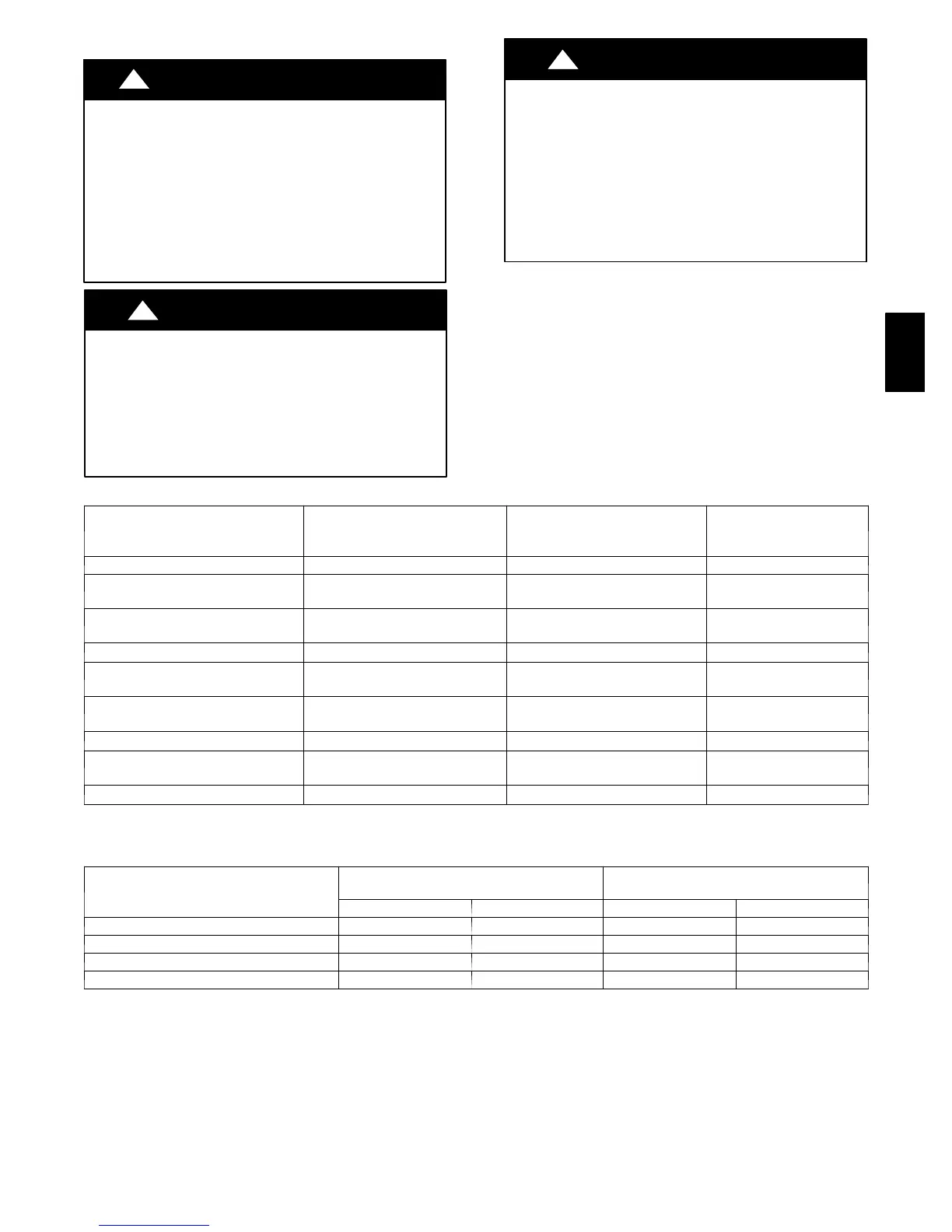
Table 1—Accessory Usage
Accessory
REQUIRED FOR LOW---AMBI-
ENT APPLICATIONS
(Below 55 °F)
REQUIRED FOR LONG LINE
APPLICATIONS* (Over 80 Ft.)
REQUIRED FOR SEA
COAST APPLICATIONS
(Within 2 miles)
Crankcase Heater Yes Yes No
Evaporator Freeze Thermostat
Yes
(for non---Infinity systems only)
No
No
Winter Start Control
Yes
(for non---Infinity systems only)
No
No
Accumulator No
No
No
Compressor Start Assist Capacitor
and Relay
Yes
Yes
No
Low Ambient Pressure Switch
Yes
(for non---Infinity systems only)
No
No
Support Feet Recommended
No
Recommended
Liquid Line Solenoid Valve Yes
See Long--- Line Application
Guideline
No
Ball Bearing Fan Motor Standard
Standard
Standard
* For Tubing Set lengths between 80 and 200 ft. horizontal or 20 ft. vertical differential (250 ft. Total Equivalent Length), refer to the Long Line Guidelines for Air
Conditioners and Heat Pumps u sing R---410A.
Table 2—Refrigerant Connections and Recommended Liquid and Vapor Tube Diameters (In.)
UNIT SIZE
LIQUID
VAPOR (up to 80 ft)
Connection Diameter Tube Diameter Connection Diameter Ra te d Tube Diameter
018, 024 3/8 3/8 5/8 5/8
030, 036 3/8 3/8 3/4 3/4
042, 048 3/8 3/8 7/8 7/8
060 3/8 3/8 7/8 1--1/8
Notes:
1. Tube diameters are for total equivalent lengths up to 80 ft.
2. Do not apply capillary tube or fixed orifice indoor coils to these units.
* For Tubing Set lengths between 80 and 200 ft. horizontal or 20 ft. vertical differential (250 ft. Total Equivalent Length), refer to the Longline
Guideline--- Air Conditioners an d Heat Pumps using R ---410A.
25HPA
 Loading...


