9
STEP 12 —Start--Up
CAUTION
!
UNIT OPERATION AND SAFETY HAZARD
Failure to follow this caution may result in minor personal
injury, equipment damage or improper operation.
To prevent compressor damage or personal injury,
observe the following:
S Do not overcharge system with refrigerant.
S Do not operate unit in a vacuum or at negative pressure.
S Do not disable low pressure switch in scroll compressor
applications.
S Dome temperatures may be hot.
CAUTION
!
PERSONAL INJURY HAZARD
Failure to follow this caution may result in personal injury.
Wear safety glasses, protective clothing, and gloves when
handling refrigerant and observe the following:
S Back seating service valves are not equipped with Schrader
valves. Fully back seat (counter clockwise) valve stem
before removing gage port cap.
CAUTION
!
ENVIRONMENTAL HAZARD
Failure to follow this caution may result in environmental
damage.
Federal regulations require that you do not vent refrigerant to
the atmosphere. Recover during system repair or final unit
disposal.
Follow these steps to properly start up
system:
1. After system is evacuated, fully open liquid and vapor
service valves.
2. Unit is shipped with valve stem(s) closed and caps
installed. Replace stem caps after system is opened to
refrigerant flow (back seated). Replace caps finger--tight
and tighten with wrench an additional 1/12 turn.
3. Close electrical disconnects to energize system.
4. Set room thermostat at desired temperature. Be sure set
point is below indoor ambient temperature.
5. Set room thermostat to HEAT or COOL and fan control to
ON or AUTO mode, as desired. Operate unit for 15
minutes. Check system refrigerant charge.
A06078
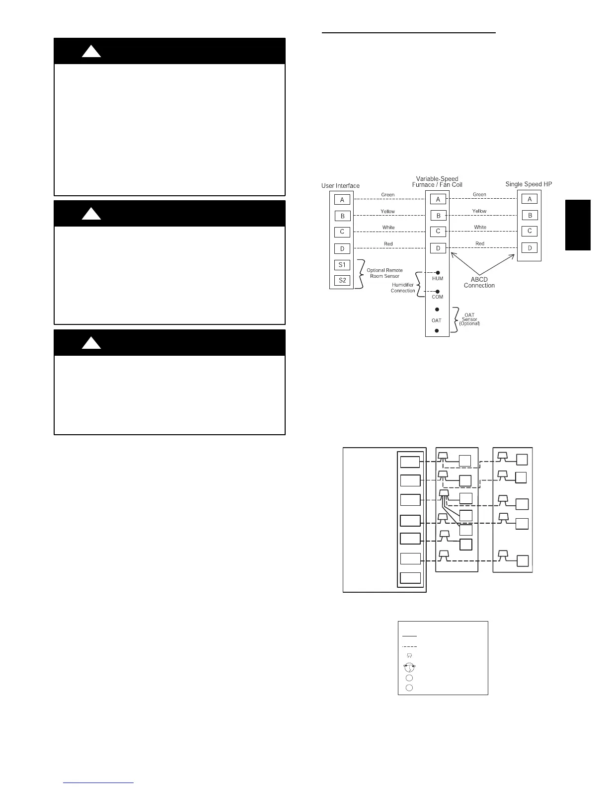
Fig. 12 --- Infinity Control Four--Wire
Connection Diagram
NOTE: Wiring must conform to NEC or local codes.
NOTE: For standard thermidistat or thermostat wiring, see
Installation Instructions for those products.
24 VAC HOT
R
C
W2
Y
G
R
C
RVS COOLING
C
W2
HP THERMOSTAT
TYPICAL
FAN COIL
HEAT
PUMP
G
O
E
W2
E
W3
R
Y
24 VAC COM
HEAT STAGE 2
COOL/HEAT
STAGE 1
INDOOR FAN
EMERGENCY
HEAT
O
*
*
*
IF AVAILABLE
*
LEGEND
24-V FACTORY WIRING
24-V FIELD WIRING
FIELD SPLICE CONNECTION
OUTDOOR THERMOSTAT
EMERGENCY HEAT RELAY
SUPPLEMENTAL HEAT RELAY
SHR
EHR
ODT
A02325 / A97413
Fig. 13 --- Generic Wiring Diagram for Standard
Thermostat Installations
25HPA
 Loading...


