Do you have a question about the Carrier 30AWH012HB and is the answer not in the manual?
Detailed technical specifications for the unit models.
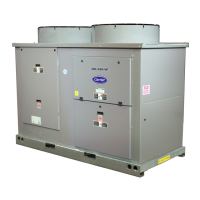
Physical dimensions and layout of the outdoor units.
Essential safety guidelines for installation and operation.
Details and precautions regarding the R-410A refrigerant.
Guidelines for making electrical connections to the unit.
Defines the operational boundaries of the unit based on temperature.
Recommended placement guidelines for the outdoor unit.
Required spacing around the unit for proper operation.
Preparatory steps before installing the unit.
Procedures and diagrams for connecting the water circuit.
Diagram illustrating the refrigerant circuit components and flow.
Wiring details for auxiliary functions and remote controls.
How the unit can be used in different heating and cooling scenarios.
Capacity ratings of the units across different operating conditions.
Schematic diagrams for electrical connections and internal wiring.
Overview of user interfaces and the unit's core control logic.
How to select operating modes and configure unit settings via NUI.
Details on freeze, high temp, short cycling, and A/C power interruption protections.
Management of pumps, dry contacts, EHS, and other system integrations.
Lists inverter alarms and error codes for specific models.
Identifies GMC board errors via LED indications and codes.
Step-by-step guides for resolving various fault codes.
Resistance values and graphs for temperature sensors and components.
How dry contacts are used for system control and inputs/outputs.
Installation and operation guide for the RC1 remote controller.
Features, settings, and functions of the CS1 programmable thermostat.
Explains interface buttons, displayed icons, and configuration codes.
Graphs showing unit performance based on outdoor and water temperatures.
Procedure for checking and charging refrigerant levels.
Instructions for cleaning the unit's heat exchanger coil.
Step-by-step guides for replacing major components.
Schedule and details for regular maintenance checks.
Information on spare parts is available in a separate document.
Graphs showing capacity and COP at different outdoor temperatures and frequencies.
Frequently asked questions and answers about refrigerants.
Special tools required for R410A installation and servicing.
| Energy Efficiency Ratio (EER) | 11.0 |
|---|---|
| Phase | 1 |
| Compressor Type | Rotary |
| Cooling Capacity | 12000 BTU |
| Refrigerant | R410A |
| Voltage | 208-230V |
| Power Supply | 208/230V, 1Ph, 60Hz |