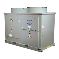
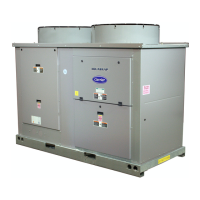
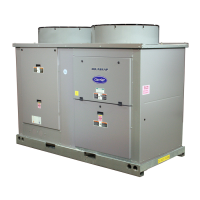
Do you have a question about the Carrier Aquasnap 30RAP080 and is the answer not in the manual?
Product overview for AQUASNAP® 30RAP010-090 air-cooled chillers with PURON® refrigerant.
Highlights key advantages and savings of Carrier's AquaSnap chiller design.
Details low-noise operation, proven reliability, and integrated features of AquaSnap chillers.
Explains durable construction, Puron® refrigerant, and ComfortLink™ controls.
Discusses footprint minimization, Novation® heat exchangers, and advanced technologies.
Details options that are installed at the factory for immediate use.
Describes fan options for cost-effectiveness and noise reduction.
Details the digital compressor option for incremental capacity modulation.
Details dimensions for the accessory storage tank for 010-015 unit sizes.
Details dimensions for the accessory storage tank for 018-030 unit sizes.
Details dimensions for the accessory storage tank for 035-060 unit sizes.
Graphs showing water pressure drop vs. GPM for 30RAP010-030.
Graphs showing water pressure drop vs. GPM for 30RAP070-090.
Graphs showing water pressure drop vs. liters/second for 30RAP010-030.
Graphs showing water pressure drop vs. liters/second for 30RAP035-060.
Graphs showing water pressure drop vs. liters/second for 30RAP070-090.
Graphs showing water pressure drop vs. GPM for units without hydronic package.
Graphs showing water pressure drop vs. GPM for units without hydronic package.
Graphs showing water pressure drop vs. liters/second for units without hydronic package.
Graphs showing water pressure drop vs. liters/second for units without hydronic package.
Graphs showing water pressure drop vs. liters/second for units without hydronic package.
Graphs showing water pressure drop vs. GPM for single pump hydronic units.
Graphs showing water pressure drop vs. GPM for single pump hydronic units.
Graphs showing water pressure drop vs. liters/second for single pump hydronic units.
Graphs showing water pressure drop vs. liters/second for single pump hydronic units.
Graphs showing water pressure drop vs. liters/second for single pump hydronic units.
Graphs showing water pressure drop vs. GPM for dual pump hydronic units.
Graphs showing water pressure drop vs. GPM for dual pump hydronic units.
Graphs showing water pressure drop vs. liters/second for dual pump hydronic units.
Graphs showing water pressure drop vs. liters/second for dual pump hydronic units.
Graphs showing water pressure drop vs. liters/second for dual pump hydronic units.
Shows pump performance curves for 1.5 and 3.0 Hp hydronic packages.
Shows pump performance curves for 5.0 Hp hydronic packages.
Shows pump performance curves for 5.0 Hp hydronic packages.
Shows pump performance curves for 7.5 and 10.0 Hp hydronic packages.
Shows pump performance curves for 3 and 5 Hp units (070-090).
Shows pump performance curves for 7.5, 10, and 15 Hp units.
Shows pump performance curves for dual pump 3 Hp.
Shows pump performance curves for dual pump 5, 7.5, 10, and 15 Hp.
Shows pump performance curves for dual pump 7.5 and 10 Hp.
Graphs illustrating pressure drop vs. flow rate for storage tanks.
Diagrams for units without a hydronic package, using size 030 as an example.
Diagrams for units with a hydronic package, using size 030 as an example.
Diagrams for units without a hydronic package, using size 060 as an example.
Diagrams for units with a hydronic package, using size 060 as an example.
Diagrams for units without a hydronic package, using size 070-090 as an example.
Diagrams for units with a hydronic package, using size 070-090 as an example.
Detailed diagram showing hydronic system components and connections.
Electrical specifications for units with single point power and no hydronic package.
Electrical specs for dual point power, low sound fans, no hydronic package.
Electrical specs for dual point power, value sound fans, no hydronic package.
Electrical data for dual point hydronic units with standard low sound fans.
Electrical data for dual point hydronic units with standard low sound fans.
Electrical data for single point hydronic units with optional value sound fans.
Electrical data for single point hydronic units with optional value sound fans.
Electrical data for dual point hydronic units with optional value sound fans.
Full load amps for standard fans with single point power.
Full load amps for optional fans with single point power.
Full load amps for standard fans with dual point power.
Full load amps for optional fans with dual point power.
Full load amps for pump options across various HP and voltages.
Details maximum field wiring sizes for different connection types.
Outlines incoming power options for standard and high SCCR terminal blocks.
Provides electrical data for accessory storage tanks.
Lists RLA and LRA for compressors based on unit voltage and circuit.
Explains the function and operation of the ComfortLink™ microprocessor.
Describes the unit's behavior during off-cycle and start-up sequences.
Explains how capacity is controlled through compressor cycling and unloading.
Lists the standard capacity control steps available for different 30RAP unit sizes.
Details features that prevent compressor cycling and ensure flow.
Explains temperature reset options and demand limiting capabilities.
Covers default settings, EXV operation, and diagnostic capabilities.
Explains ice duty capabilities and benefits of thermal storage systems.
Guidelines for siting chillers, including clearances and sound considerations.
Recommendations for installing multiple chillers in parallel configurations.
Procedures for water system cleaning and cooler operational limits.
Information on recirculation flow and maximum cooler flow rates.
Explains variable speed pumping and hydronic package options.
Importance of air management in water loops and fluid volume requirements.
Minimum fluid volume requirements and details on accessory storage tanks.
Information on fouling factors and freeze protection for coolers.
Table showing minimum and maximum cooler flow rates in gpm and l/s.
Guidance on altitude corrections and closed-loop water system design.
Procedures for cleaning water systems and water quality limitations.
Details on condenser coil protection options like Enviro-Shield™.
Information on energy management practices and demand limiting.
Explanation of bypass flow and variable flow rate application.
Diagram of a typical multiple chiller setup with air eliminator and expansion tank.
General information on system description, quality assurance, and unit construction.
Guidelines for unit delivery, storage, and handling procedures.
General equipment specifications including chassis, cabinet, and fans.
Specifications for compressors, including type, mounting, and staging.
Details on the cooler specifications, including rating, construction, and options.
Specifications for the air-cooled Novation® heat exchanger condenser coils.
Lists refrigeration components and unit control functions.
Details unit safeties and operating characteristics.
Specifications for fan motors and electrical power supply requirements.
Describes the control panel's diagnostic capabilities and information display.
Covers unit operating characteristics and fan motor specifications.
Details electrical requirements and chilled water circuit specifications.
Specifies the Chillervisor System Manager for multi-unit control.
Details the digital compressor option for enhanced temperature control.
Describes the remote cooler kit for flexible unit placement.
Explains the function of wind baffles for low ambient operation.
Details the BACnet communication option for system integration.
Describes the portable Navigator™ display module for diagnostics.
Details the GFI convenience outlet option.
Specifies cooler heater function for freeze protection.
Describes features for significant chiller sound reduction.
Details suction service valves for compressor isolation.
| Brand | Carrier |
|---|---|
| Model | Aquasnap 30RAP080 |
| Category | Air Conditioner |
| Language | English |


 Loading...