2
User interface
Abbreviations / Meanings ...................................................... 2
Safety consideration................................................................. 2
Introduction ................................................................................ 2
Abbreviations / Meanings ...................................................... 2
Installation consideration ....................................................... 3-11
Models ..................................................................................... 3
Power ....................................................................................... 3
Installation ................................................................................... 3
Step 1 — User Interface Location.................................. 3
Step 2 — Install User Interface ....................................... 3
Installation (Table 1) ................................................................. 6
Step 3 — Set NUI Installer Conguration ................... 6
Climatic Curves........................................................................... 12
Pre-Set Curves ...................................................................... 12
Climatic Custom Curves .......................................................... 14
Heating Curve Adaptation ..................................................... 15
Factory Conguration Mode ................................................. 15
Factory Conguration Mode (Table 2) ............................... 16
Clock............................................................................................... 16
Operational and connection information ........................ 16
Error Codes ............................................................................ 16
Fault Code Table .................................................................. 17
Wiring Diagram .......................................................................... 18
User Interface Conguration Record .................................. 18-19
Safety consideration
Introduction
Abbreviations / Meanings
Contents Page
Read and follow manufacturer instructions carefully. Follow
all local electrical codes during installation. All wiring must
conform to local and national electrical codes.
Improper wiring or installation may damage the NUI.
Understand the signal words DANGER, WARNING, and
CAUTION. These words are used with the safety--alert
symbol. DANGER identies the most serious hazards which
will result in severe personal injury or death. WARNING
signies a hazard which could result in personal injury or
death. CAUTION is used to identify unsafe practices which
may result in minor personal injury or product and property
damage.
NOTE is used to highlight suggestions which will result in
enhanced installation, reliability, or operation.
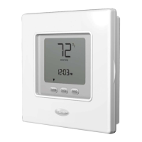
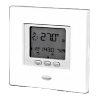
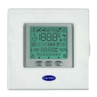
Carrier’s NUI series programmable user interface is wall--
mounted, low--voltage user interface which maintains room
temperature by controlling the operation of a heating and/
or air conditioning system. “Heat pump”, “ Air conditioner”
and “Heat only” are available, with the present versions. A
variety of features are provided including separate heating
and cooling set-points, keypad lockout, backlighting, and
built--in installer test etc. Programming features include
7--day (all days the same), 5/2 (Mon--Fri and Sat--Sun) and
1-day (all 7 days individually) with 2 or 4 or 6 periods per
day.
This Installation Instruction covers installation,
conguration, and startup of NUI. For operational details,
consult the Owner’s Manual.
NUI User Interface Comfort Series 33AW-CS1
SUI User Interface 33AW-RC1
CC Climatic Curve
CDU Compressor Device Unit
GMC Global Module controls
Stb. Stand by
LWT Leaving water Temperature
EWT Enter water Temperature
REFR. Refrigerant Temperature
TE Outdoor Heat Exchange Sensor
TD Discharge Temperature Sensor
WSP Water Set Point
HP Heat Pump
OAT Outdoor Air Temperature
FR Mode Frequency Reduction
TO Outdoor Temperature Sensor
TR Refrigerant Temperature Sensor
(Placed between the electronic expansion
valve and the Air to Water heat exchanger)
TS Suction Temperature Sensor
129H45_GB_print2.indd 2 20/09/11 12.53
 Loading...