EasyManua.ls Logo

Carrier 33ZCFANTRM User Manual

Carrier 33ZCFANTRM
52 pages
To Next Page IconTo Next Page
Page #1 background imageLoading...
Page #1 background image
Manufacturer reserves the right to discontinue, or change at any time, specifications or designs without notice and without incurring obligations.
PC 111 Catalog No. 533-355 Printed in U.S.A. Form 33ZC-1SI Pg 1 303 11-99 Replaces: New
Book 1 4
Ta b 1 1 a 1 3 a
Installation, Start-Up and
Configuration Instructions
Part Numbers 33ZCFANTRM, 33ZCVAVTRM, 33ZCSECTRM
CONTENTS
Page
SAFETY CONSIDERATIONS
. . . . . . . . . . . . . . . . . . . . . . 1
GENERAL
. . . . . . . . . . . . . . . . . . . . . . . . . . . . . . . . . . . . . . . . 2
INSTALLATION
. . . . . . . . . . . . . . . . . . . . . . . . . . . . . . . . 2-29
General
. . . . . . . . . . . . . . . . . . . . . . . . . . . . . . . . . . . . . . . . . . 2
Zone Controller Hardware
. . . . . . . . . . . . . . . . . . . . . . . . 2
Field-Supplied Hardware
. . . . . . . . . . . . . . . . . . . . . . . . . 2
SPACE TEMPERATURE SENSOR
PRIMARY AIR TEMPERATURE SENSOR
SUPPLY AIR TEMPERATURE (SAT) SENSOR
RELATIVE HUMIDITY SENSOR
INDOOR AIR QUALITY (CO
2
) SENSOR
Mount Zone Controller
. . . . . . . . . . . . . . . . . . . . . . . . . . . 4
LOCATION
MOUNTING
Connect the Power Transformer
. . . . . . . . . . . . . . . . . . 7
Connect Airflow Pickups
. . . . . . . . . . . . . . . . . . . . . . . . . 7
Install Sensors
. . . . . . . . . . . . . . . . . . . . . . . . . . . . . . . . . . 19
SPACE TEMPERATURE SENSOR INSTALLATION
PRIMARY AIR TEMPERATURE SENSOR
INSTALLATION
SUPPLY AIR TEMPERATURE (SAT) SENSOR
INSTALLATION
INDOOR AIR QUALITY SENSOR INSTALLATION
HUMIDITY SENSOR (WALL-MOUNTED)
INSTALLATION
Remote Occupancy Contact
. . . . . . . . . . . . . . . . . . . . . 26
Connect the Outputs
. . . . . . . . . . . . . . . . . . . . . . . . . . . . 26
Modulating Baseboard Hydronic Heating
. . . . . . . . 26
Connect the CCN Communication Bus
. . . . . . . . . . 26
COMMUNICATION BUS WIRE SPECIFICATIONS
CONNECTION TO THE COMMUNICATION BUS
START-UP
. . . . . . . . . . . . . . . . . . . . . . . . . . . . . . . . . . . . 29-31
Perform System Check-Out
. . . . . . . . . . . . . . . . . . . . . 29
Network Addressing
. . . . . . . . . . . . . . . . . . . . . . . . . . . . . 30
Initial Operation and Test
. . . . . . . . . . . . . . . . . . . . . . . . 30
Airflow Check
. . . . . . . . . . . . . . . . . . . . . . . . . . . . . . . . . . . 30
Fan and Heat Configuration and Test
. . . . . . . . . . . . 30
CONFIGURATION
. . . . . . . . . . . . . . . . . . . . . . . . . . . . 31-50
Points Display Screen
. . . . . . . . . . . . . . . . . . . . . . . . . . . 31
Modify Controller Configuration
. . . . . . . . . . . . . . . . . 32
ALARM LIMIT CONFIGURATION SCREEN
CONTROLLER IDENTIFICATION SCREEN
HOLIDAY CONFIGURATION SCREENS
LINKAGE COORDINATOR CONFIGURATION
SCREEN
OCCUPANCY CONFIGURATION SCREEN
SET POINT SCREEN
Service Configuration Selection Screen
. . . . . . . . . 37
AIRFLOW SERVICE CONFIGURATION SCREEN
TERMINAL SERVICE CONFIGURATION SCREEN
OPTIONS SERVICE CONFIGURATION SCREEN
SECONDARY DAMPER SERVICE
CONFIGURATION SCREEN
Maintenance Table Menu Screen
. . . . . . . . . . . . . . . . 43
LINKAGE MAINTENANCE TABLE
OCCUPANCY MAINTENANCE TABLE
ZONE AIR BALANCE/COMMISSIONING TABLE
ZONE MAINTENANCE TABLE
SAFETY CONSIDERATIONS
SAFETY NOTE
Air-handling equipment will provide safe and reliable
service when operated within design specifications. The
equipment should be operated and serviced only by
authorized personnel who have a thorough knowledge
of system operation, safety devices and emergency
procedures.
Good judgement should be used in applying any manu-
facturers instructions to avoid injury to personnel or dam-
age to equipment and property.
Disconnect all power to the unit before performing mainte-
nance or service. Unit may automatically start if power is
not disconnected. Electrical shock and personal injury
could result.
If it is necessary to remove and dispose of mercury contac-
tors in electric heat section, follow all local, state, and fed-
eral laws regarding disposal of equipment containing
hazardous materials.
Single Duct Air Terminal Zone Controller
VAV Fan Terminal Zone Controller
Secondary Terminal Zone Controller

Table of Contents

Question and Answer IconNeed help?

Do you have a question about the Carrier 33ZCFANTRM and is the answer not in the manual?

Carrier 33ZCFANTRM Specifications

General IconGeneral
Voltage24 VAC
BacklightYes
Power Source24V
ProgrammabilityProgrammable
TypeWall Mounted
Temperature Range40°F to 90°F
MountingWall Mount

Summary

Installation, Start-Up and Configuration Instructions

SAFETY CONSIDERATIONS

Important safety precautions before installation and operation.

INSTALLATION

Covers the physical setup and wiring of the zone controller.

START-UP

Procedures for initial setup and verification of the controller.

CONFIGURATION

Details on setting up controller parameters and options.

GENERAL CONTROLLER INFORMATION

Zone Controller Hardware

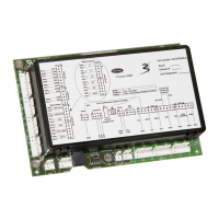
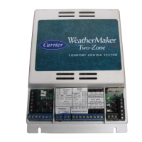
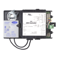
Description of the physical components of the controller.

Field-Supplied Hardware

Lists components that must be provided by the installer.

INSTALLATION BASICS

Covers general installation and sensor setup procedures.

Mount Zone Controller

LOCATION AND MOUNTING

Details on placement, mounting, and clearance.

POWER AND AIRFLOW CONNECTIONS

SENSOR INSTALLATION AND WIRING

SPACE TEMPERATURE SENSOR

Step-by-step guide for SPT sensor installation and wiring.

CCN NETWORK SERVICE JACK

Instructions for connecting the CCN service jack.

AIRFLOW PICKUP INSTALLATION

SPACE TEMPERATURE SENSOR MOUNTING

SPACE TEMPERATURE SENSOR WIRING

COMMUNICATION BUS WIRING

PRIMARY AND SUPPLY AIR SENSOR INSTALLATION

INDOOR AIR QUALITY SENSOR INSTALLATION

Instructions for installing the IAQ sensor.

IAQ AND HUMIDITY SENSOR WIRING

ZONE CONTROLLER WIRING OPTIONS

CCN COMMUNICATION BUS CONNECTION

Connecting to the CCN bus and specifications.

START-UP PROCEDURES

SYSTEM CHECK-OUT

Verifying all connections and installations.

NETWORK ADDRESSING

Setting up network communication addresses.

CONFIGURATION PARAMETERS

POINTS DISPLAY SCREEN

Viewing the status of controller points.

TERMINAL CONFIGURATION SETTINGS

Configuring terminal mode, type, and setpoints.

CONTROLLER SETTINGS OVERVIEW

CONTROLLING SETPOINT

Setting the primary temperature set point.

SPACE TEMPERATURE

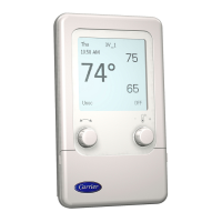
Information about the space temperature sensor.

PRIMARY AIRFLOW

Data related to primary airflow.

CONTROLLER CONFIGURATION MENUS

ALARM LIMIT CONFIGURATION

Configuring alarm settings for the controller.

ALARM CONFIGURATION SETTINGS

SPACE TEMPERATURE ALARMS

Settings for occupied/unoccupied temperature alarms.

HUMIDITY AND IAQ ALARMS

Settings for humidity and indoor air quality alarms.

LINKAGE COORDINATOR CONFIGURATION

AIR SOURCE CONFIGURATION

Defining the air source bus and element number.

SENSOR DATA SHARING AND OCCUPANCY CONFIGURATION

TEMPERATURE SENSOR GROUPING

Configuring how temperature sensors are shared.

OCCUPANCY CONFIGURATION SCREEN

Setting up occupancy schedules.

SET POINT CONFIGURATION

OCCUPIED AND UNOCCUPIED SET POINTS

Configuring heating and cooling set points.

AIRFLOW SETTINGS AND SERVICE SELECTION

AIRFLOW SERVICE CONFIGURATION

Configuring pressure independent airflow set points.

TERMINAL SERVICE CONFIGURATION

TERMINAL TYPE AND DUCT SIZING

Specifying terminal type and inlet dimensions.

PRESSURE DEPENDENT SETTINGS

Configuring backup settings for pressure transducer failure.

PROBE MULTIPLIER AND CALIBRATION

CALIBRATION GAIN ADJUSTMENT

Fine-tuning airflow calculation gain.

OFFSET ADJUSTMENT

Adjusting minimum airflow precision.

DAMPER LOOP AND HEAT PARAMETERS

DAMPER LOOP PARAMETERS

Configuring proportional, integral, and rotation settings.

HEATING LOOP PARAMETERS

Configuring heating loop gains.

CONTROL OPTIONS AND SERVICE SCREENS

OPTIONS SERVICE CONFIGURATION

Configuring occupancy schedules and global settings.

ADVANCED CONTROL CONFIGURATIONS

CONTROL OPTIONS AND SENSORS

Selecting sensors and configuring control parameters.

SECONDARY DAMPER CONFIGURATION

Configuring secondary damper settings.

SECONDARY DAMPER AND MAINTENANCE TABLES

SECONDARY DUCT SIZE AND AREA

Inputting dimensions for secondary duct.

MAINTENANCE TABLE MENU

Accessing various maintenance tables.

LINKAGE MASTER STATUS AND ZONE DATA

OPERATING MODE AND SUPPLY TEMPERATURE

Displaying operating mode and supply air temp.

AVERAGE ZONE SET POINTS AND TEMPERATURES

Displaying averages of zone set points and temperatures.

LINKAGE MAINTENANCE SCREEN DATA

UNOCCUPIED STATUS AND TIMES

Displaying unoccupied status and times.

DAMPER POSITION AND PRESSURE SETTINGS

Displaying damper position and pressure settings.

OCCUPANCY MAINTENANCE DATA

OCCUPIED AND UNOCCUPIED TIME DISPLAY

Displaying occupied and unoccupied start/end times.

ZONE AIR BALANCE AND COMMISSIONING

COMMISSIONING MODE AND DAMPER CALIBRATION

Setting commissioning mode and calibrating dampers.

AIRFLOW CALIBRATION

Calibrating airflow settings.

ZONE AIR BALANCE/COMMISSIONING TABLE DATA

HEATING OVERRIDE AND AIRFLOW SET POINTS

Testing heating and displaying airflow set points.

ACTUAL AIRFLOW AND DAMPER POSITION

Displaying actual airflow and damper position.

Related product manuals