14
Table 6 — Thermistor Resistance vs Temperature Values for
Supply-Air Temperature Sensor, Primary Air Temperature Sensor and Space Temperature Sensor
SPACE TEMPERATURE SENSOR INSTALLATION AND
WIRING — The space temperature (SPT) sensor accessory is
ordered separately for field installation. It is installed on
interior walls to measure room space air temperature. See
Fig. 16-20 and Table 6.
The wall plate accommodates both the NEMA (National
Electrical Manufacturing Association) standard and the Euro-
pean
1
/
4
DIN standard. The use of a junction box to accommo-
date the wiring is recommended for installation. The sensor
may be mounted directly on the wall, if acceptable by local
codes.
DO NOT mount the sensor in drafty areas such as near heat-
ing or air-conditioning ducts, open windows, fans, or over heat
sources such as baseboard heaters or radiators. Sensors mount-
ed in those areas will produce inaccurate readings.
Avoid corner locations. Allow at least 3 ft between the sen-
sor and any corner. Air in corners tends to be stagnant, resulting
in inaccurate sensor readings.
Sensor should be mounted approximately 5 ft up from the
floor, in an area that best represents the average temperature
found in the space (zone).
The space temperature sensor cover includes a service jack
connector. If wiring connection is made to the service jack, the
connector can then be used to connect a network service tool
with the Carrier Comfort Network® system.
Before installing the space temperature sensor, decide
whether or not the service jack wiring connection will be made.
If connection is desired, the CCN communication cable should
be available at time of sensor installation, for convenient
wiring connections. The cable selected must meet the
requirements for the entire network. See Connect the CCN
Communication Bus section for CCN communication cable
specifications.
RESISTANCE
(Ohms)
TEMP
(F)
RESISTANCE
(Ohms)
TEMP
(F)
RESISTANCE
(Ohms)
TEMP
(F)
RESISTANCE
(Ohms)
TEMP
(F)
RESISTANCE
(Ohms)
TEMP
(F)
29481 32 17050 54 10227 76 6340 98 4051 120
28732 33 16646 55 10000 77 6209 99 3972 121
28005 34 16253 56 9779 78 6080 100 3895 122
27298 35 15870 57 9563 79 5954 101 3819 123
26611 36 15497 58 9353 80 5832 102 3745 124
25943 37 15134 59 9148 81 5712 103 3673 125
25295 38 14780 60 8948 82 5595 104 3603 126
24664 39 14436 61 8754 83 5481 105 3533 127
24051 40 14101 62 8563 84 5369 106 3466 128
23456 41 13775 63 8378 85 5260 107 3400 129
22877 42 13457 64 8197 86 5154 108 3335 130
22313 43 13148 65 8021 87 5050 109 3272 131
21766 44 12846 66 7849 88 4948 110 3210 132
21234 45 12553 67 7681 89 4849 111 3150 133
20716 46 12267 68 7517 90 4752 112 3090 134
20212 47 11988 69 7357 91 4657 113 3033 135
19722 48 11717 70 7201 92 4564 114 2976 136
19246 49 11452 71 7049 93 4474 115 2920 137
18782 50 11194 72 6900 94 4385 116 2866 138
18332 51 10943 73 6755 95 4299 117 2813 139
17893 52 10698 74 6613 96 4214 118 2761 140
17466 53 10459 75 6475 97 4132 119
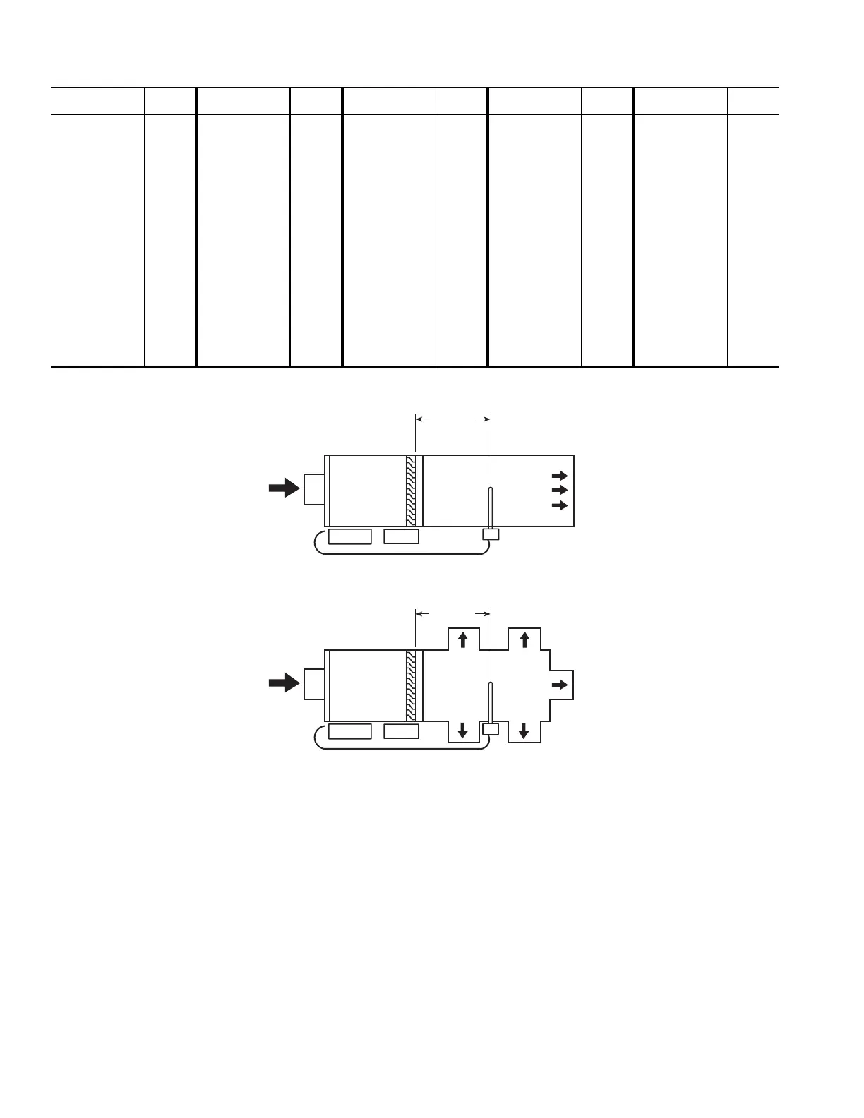
ZC
AIR
TERMINAL
UNIT
MULTIPLE
OUTLET
ATTENUATOR
HEAT
SAT
2 FT. MIN.
PRIMARY
AIR INLET
ZC
AIR
TERMINAL
UNIT
HEAT
SAT
2 FT. MIN.
PRIMARY
AIR INLET
LEGEND
Fig. 15 — Supply Air Temperature Probe (Part No. 33ZCSENSAT) Locations
SAT — Supply Air Temperature Sensor
ZC — Zone Controller
UNIT WITH ELECTRIC HEAT
UNIT WITH MULTIPLE OUTLET ATTENUATOR