Installation — After completing the pre-installation steps,
proceeds as follows:
MOUNT CONTROL ASSEMBLY
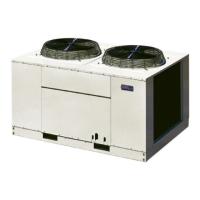
1. See Fig. 11 for the location of the access panel and Motor-
master® low-ambient control in the bottom of the unit.
Remove the access panel.
2. Using the template supplied in this document, drill pilot
holes for mounting the low-ambient control.
When drilling holes, be careful not to damage return coil
bends inside unit.
3. Fasten control to unit with four no. 10 sheet metal screws
and star lockwashers provided. Lockwashers are re-
quired to ensure electrical ground with condensing unit.
MOUNT SENSOR ASSEMBLY
The sensor assembly is fragile. Handle with care.
1. See Fig. 12 to determine where to locate sensor on coil
return bend. As shown in Fig. 13, fasten sensor to return
bend with the supplied screw, plate washers, and nut. See
Table 1 for sensor temperature vs resistance values.
2. Coil and secure excess wire inside the unit near the sen-
sor or next to the low ambient control; provide additional
protection against abrasion or movement of the wire if
necessary.
3. Reinstall the access panel.
Table 1 — Sensor (Thermistor) Temperature
vs Resistance
TEMPERATURE
NOMINAL RESISTANCE
(Ohms)
FC
60 16 7750
70 21 5900
77 25 5000
80 27 4650
90 32 3650
100 38 2875
110 43 2275
120 49 1850
Fig. 11 — Location of Motormaster Low-Ambient Control
11
 Loading...