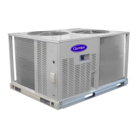
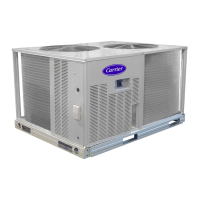
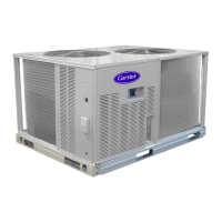
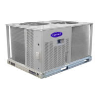
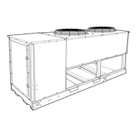
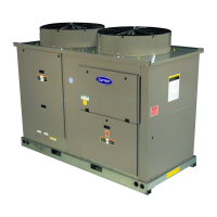
BASE UNIT DIMENSIONS – 38AUM Series Size Z07-D14
NOTES:
1. Minimum clearance (Local codes or jurisdiction may prevail):
A. Bottom to combustible surfaces: 0 inches
B. Outdoor coil, for proper airflow: 36 inches one side, 12 inches the other. The side getting the greater clearance is optional.
C. Overhead: 60 inches, to assure proper outdoor fan operation.
D. Between units: Control box side: 42 inches per NEC.
E. Between unit and ungrounded surfaces: Control box side, 36 inches per NEC.
F. Between unit and block or concrete walls and other grounded surfaces: Control box side 42 inches per NEC.
2. With exception of the clearance for the outdoor coil as stated in note 1B, are movable fence or barricade requires no clearance.
3. Units may be installed on combustible floors made from wood or Class A, B or C roof covering material.
Unit
38AUM
Unit
Weight
(kg)
Height (mm)
Service Valve
Connections
H X Y Z Suction Liquid
Z07 176.0 1165.0 457.2 609.6 533.4 1-1/8 3/8
Z08 177.0 1165.0 457.2 609.6 533.4 1-1/8 1/2
D12 234.0 1368.0 482.6 584.2 609.6 1-1/8 3/8
D14 297.0 1368.0 508.0 635.0 609.6 1-3/8 1/2
RIGHT SIDE VIEW
- Direction of Air Flow
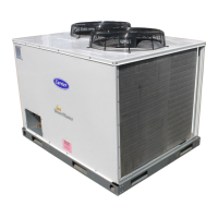
 Loading...
