Table 4 - Refrigerant Charge Adjustments
Liquid Line
Size
Puron Charge
(oz/
ft
)
3/8 0.60 (Factory charge for lineset = 13.5 oz (382.7)
5/16
0.40
1/4
0.27
Units are factory charged for 25 ft (7.6 m) of 3/8” liquid line. The factory charge for 3/8” lineset 9 oz (266.2 g). When using other length or
diameter liquid lines, charge adjustments are required per the chart above.
Charging Formula:
[(Lineset oz/ft x total length) – (factory charge for lineset)] = charge adjustment
Example 1: System has 25ft of line set using existing 1/4“liquid line. What charge adjustment is required?
Formula: (.27 oz/ft x 25ft) – (13.5 oz) = -6.75 oz; (8.0 g/m x 7.6 m) – (382.7 g) = -321.9 g
Net result is to remove 6.75 oz of refrigerant from the system
Example 2: System has 45 ft of existing 5/16” liquid line. What is the charge adjustment?
Formula: (.40 oz/ft. x 45ft) – (13.5 oz.) = 9 oz; (11.8 g/m x 13.7m) – (382.7 g) = -221.0 g
Net result is to add 4.5 oz of refrigerant to the system
LSV (Heat Pump
Only)
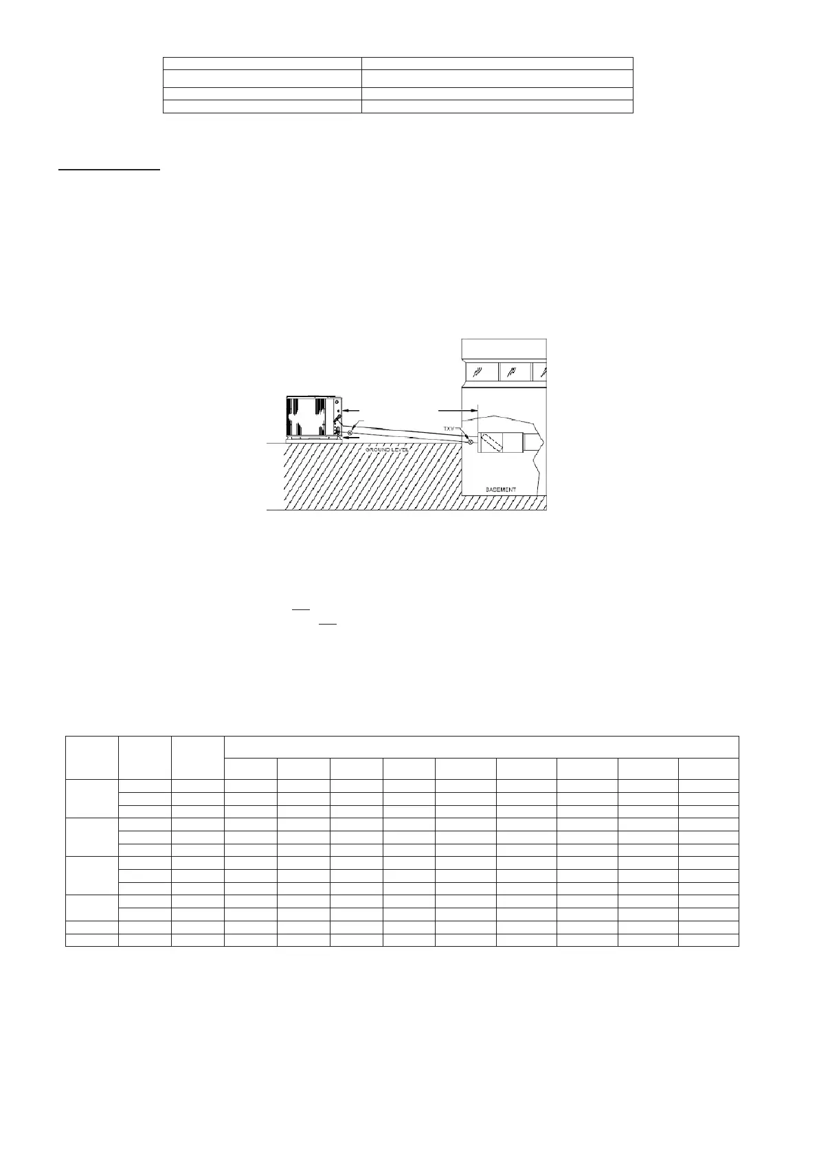
Fig. 2 – Equal– Level Outdoor/Indoor Unit
• A TXV with 15 to 30% bleed must be installed at indoor unit when application qualifies as long line. See Table 6.
• Hard Start Kit (start capacitor and relay) must be installed on outdoor unit when application qualifies as long line. See Table 6.
• A crankcase heater must be installed on compressor when the application qualifies as long line. See Table 6 .
• Vapor line should slope towards indoor unit.
• Maximum actual liquid line is up to 100 (61 m). See Table 5.
• Maximum total equivalent length is up to 120 (76.2 m). See Table 5.
• Heat pump only – Bi- flow liquid line solenoid must be installed within 2 ft (0.61 m) of outdoor unit with arrow pointing towards
outdoor unit.
•
Heat pump only – Outdoor AccuRater
TM
adjustment not required
• Use vapor line per Tables 3.
• Use liquid lines per Table 5.
Table 5 – Maximum Total Equivalent Length
Equal Level or Outdoor Unit Below Indoor
Size
System
Ty
pe
Liquid
Line
Diameter
w/ TX
V
Maximum Total Equivalent L
e
n
g
th**
:
Outdoor unit BELOW
I
n
door
Vertical Separation ft
(
m
)
0
---
5
(0
---
1.
5)
6
---
10
(1.8
---
3.
0)
11
---
20
(3.4
---
6.
1)
21
---
30
(6.4
---
9.
1)
31
---
40
(9.4
---
12.
2)
41
---
50
(12.5
---
15.
2)
51
---
60
(15.5
---
18.
3)
61
---
70
(18.6
---
21.
3)
71
---
80
(21.6
---
24.
4)
18000
AC
Only
1/4
150*
150*
125 100 100 75 ---
---
---
---
---
---
AC
Only
5/16
150*
150*
150*
150*
150*
150*
150*
150*
150
AC/HP
3/8
150*
150*
150*
150*
150*
150*
150*
150*
150*
24000
AC
Only
1/4
75 75 75 50 50 ---
---
---
---
---
---
---
---
AC
Only
5/16
150*
150*
150*
150*
150*
150*
150*
125 100
AC/HP
3/8
150*
150*
150*
150*
150*
150*
150*
150*
150*
30000
AC
Only
1/4
30 ---
---
---
---
---
---
---
---
---
---
---
---
---
---
---
---
AC
Only
5/16
150*
125*
100 150 125 100 75 ---
---
---
---
AC/HP
3/8
150*
150*
150*
150*
150*
150*
150*
150*
150*
36000
AC
Only
5/16
150*
150*
150*
100 100 100 75 ---
---
---
---
AC/HP
3//8
150*
150*
150*
150*
150*
150*
150*
150*
150*
48000
AC/HP
3/8
150*
150*
150*
150*
150*
150*
150*
150*
---
---
60000
AC/HP
3/8
150*
150*
150*
150*
150*
150*
150*
---
---
---
---
*
Maximum actual length not to exceed 100ft
**
Total equivalent length accounts for losses due to elbows or fitting. See the Table 2 for
de
tails.
--- ---
=
outside acceptable r
a
n
ge
 Loading...


