Table 6 – AC / HP with Puron® Refrigerant Long Line Description ft (m)
Beyond these lengths, long line accessories are required
AC
AC Liquid Line
Size
Units On Same
L
evel
1/4
No accessories needed within allowed
lengths
5/16
120 (36.6)
HP
3/8
80 (24.4)
See Table 8 f or
Maximum
Height and
Equivalent
Length
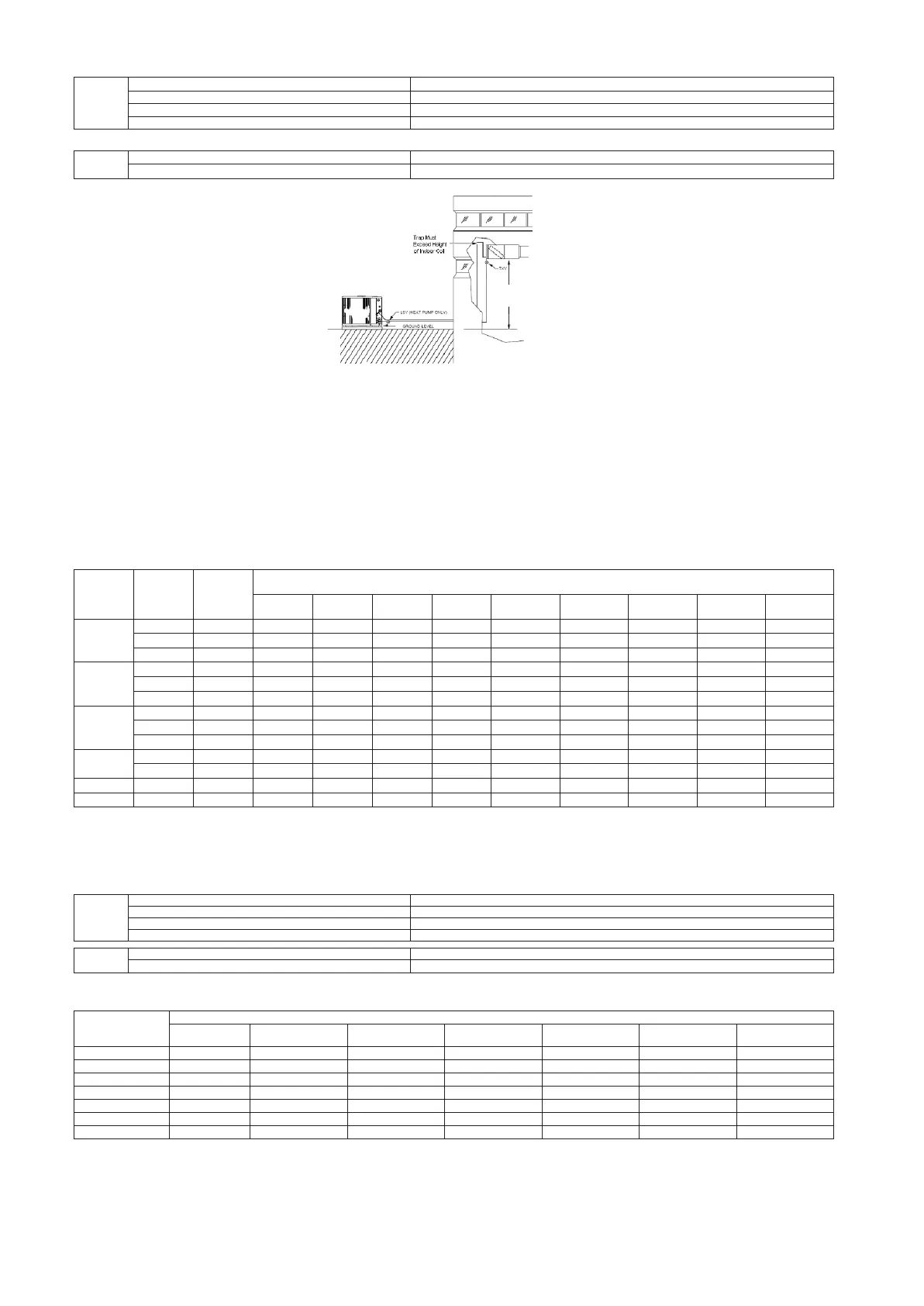
Fig. 3 – Outdoor Unit Below Indoor Unit
• Unit must be charged to 10° subcooling or nameplate subcooling, whichever is greater.
• A TXV with 15 to 30% bleed must be installed at indoor unit when application qualifies as long line. See Table 8.
• A crankcase heater must be installed on compressor when the application qualifies as long line. See Table 8.
• Hard Start Kit (start capacitor and relay) must be installed in outdoor unit when the application qualifies as long line. See Table 8.
• An inverted vapor- line trap must be installed at indoor unit. The top peak of trap must be greater than height of indoor coil.
• Ma
ximum actual liquid line length is up to See Table 7 for maximum total equivalent length.
• Heat pump only – Bi- flow liquid line solenoid must be installed within 2 ft (0.61 m) of outdoor unit with arrow pointing towards outdoor unit.
• Heat pump only – Adjust outdoor piston per Table 9.
• Use vapor line per Tables 3.
• Use liquid lines per Table 7.
Table 7 - Maximum Total Equivalent Length
**
Outdoor Unit Below Indoor Unit
Size
System
Ty
pe
Liquid
Line
Diameter
w/ TX
V
Maximum Total Equivalent L
e
n
g
th
{
:
Outdoor unit BELOW
I
n
door
Vertical Separation ft
(
m
)
0
---
5
(0
---
1.
5)
6
---
10
(1.8
---
3.
0)
11
---
20
(3.4
---
6.
1)
21
---
30
(6.4
---
9.
1)
31
---
40
(9.4
---
12.
2)
41
---
50
(12.5
---
15.
2)
51
---
60
(15.5
---
18.
3)
61
---
70
(18.6
---
21.
3)
71
---
80
(21.6
---
24.
4)
18000
AC Only
1/4
150 150 125 100 100 75 ---
---
---
---
---
---
AC Only
5/16
150*
150*
150*
150*
150*
150*
150*
150*
150
*
AC/HP
3/8
150*
150*
150*
150*
150*
150*
150*
150*
150*
24000
AC Only
1/4
75 75 75 50 50 ---
---
---
---
---
---
---
---
AC Only
5/16
150*
150*
150*
150*
150*
150*
150
*
125 100
AC/HP
3/8
150*
150*
150*
150*
150*
150*
150*
150*
150*
30000
AC Only
1/4
30 ---
---
---
---
---
---
---
---
---
---
---
---
---
---
---
---
AC Only
5/16
150
*
150*
150*
150*
125 100 75 ---
---
---
---
AC/HP
3/8
150
*
150
*
150
*
150
*
150
*
150
*
150
*
150
*
150
*
36000
AC Only
5/16
150
*
150
*
150
*
100 100 100 75 ---
---
---
---
AC/HP
3//8
150
*
150
*
150
*
150
*
150
*
150
*
150
*
150
*
150
*
48000
AC/HP
3/8
150*
150*
150*
150*
150*
150*
150*
150*
---
---
60000
AC/HP
3/8
150*
150*
150*
150*
150*
150*
110 ---
---
---
---
*
Maximum actual length not to exceed 100ft
**
Total equivalent length accounts for losses due to elbows or fitting. See the Table 2 for
de
tails.
--- ---
=
outside acceptable range
Table 8 - AC / HP with Puron® Refrigerant Long Line Description ft (m)
Beyond these lengths, long line accessories are required
AC
AC Liquid Line
Size
Outdoor Below
I
n
door
1/4
No accessories needed within allowed
lengths
50 (15.2) vertical or 120 (36.6)
to
ta
l
3/8
35 (10.7) vertical or 80 (24.4)
to
ta
l
HP
HP Liquid Line
Size
Outdoor Below
I
n
door
3/8
20 (6.1) vertical or 80 (24.4)
to
ta
l
Table 9 - Puron
®
Refrigerant Heat Pump Outdoor Piston Change – Outdoor Unit BELOW Indoor Unit
Btuh
Vertical Separation ft (m) --- Outdoor BELOW Indoor
U
nit
)
0
---
19
(0
---
5.
8)
20
---
29
(6.1
---
8.
8)
30
---
39
(9.1
---
11.
9)
40
---
49
(12.2
---
14.
9)
50
---
59
(15.2
---
18.
0)
60
---
69
(18.3
---
21.
0)
70
---
80
(21.3
---
24.
4)
18,000 0
---
1
---
1
---
2
---
2
---
2
---
2
24,000 0
---
1
---
1
---
2
---
2
---
3
---
3
30,000 0
---
1
---
1
---
2
---
2
---
3
---
3
36,000 0
---
1
---
2
---
2
---
2
---
3
---
3
42,000 0
---
1
---
2
---
2
---
3
---
3
---
4
48,000 0
---
1
---
2
---
2
---
3
---
3
—
NOTE: (—) Indicates vertical separation exceeds allowable
limits.
Example 1: On a 4 ton system the outdoor unit is 60 ft (18.3 m) below the indoor unit. This is acceptable only if the total equivalent length is 230 ft (70.1 m)
o
r less.
The heating piston must be re
---
sized
---
3.
Example 2: On a 3
---
ton system the outdoor unit is 80 ft (24.4 m) below the indoor unit. This is acceptable up to 250 ft (76.2 m) total equivalent length.
T
he
heating piston must be re
---
sized
---
3.
 Loading...


