7
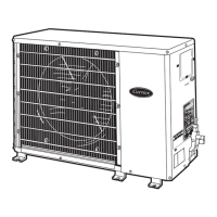
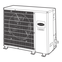
Base Unit Dimensions
38H 048-0
70
A B C D E F G H
UNIT 38H
Ft-in. mm Ft-in. mm Ft-in. mm Ft-in. mm Ft-in. mm Ft-in. mm Ft-in. mm Ft-in. mm
048-070
3-13⁄16 944.6 3-89⁄16 1131.9 1-51⁄16 433.4 1-67⁄16 468.3 2-61⁄2 774.7 1-75⁄8 498.5 1-75⁄8 498.5 2-55⁄8 752.5
NOTES:
1. Required clearances: with coil facing wall
allow 8 in. minimum clearance on coil side and
coil end, and 3 ft minimum clearance on
compressor end and fan side.
2. Dimensions in [ ] are in millimeters.
 Loading...