4
INSTALLATION
Step 1 — Complete Pre-Installation Checks
UNPACK UNIT—Move unit to final location. Remove
carton from unit, being careful not to damage service
valves or grilles.
INSPECT SHIPMENT — File claim with shipping
company if shipment is damaged or incomplete. Check
unit nameplate to ensure unit matches job requirements.
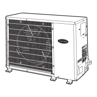
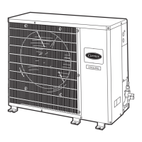
CONSIDER SYSTEM REQUIREMENTS — Consult
local building codes and NEC for special installation
requirements. Allow sufficient space for airflow
clearance, wiring, refrigerant piping, and servicing unit.
See Fig. 1 and 2. Unit can be mounted on a level pad
directly on base legs or mounted on raised pads at
support points.
WARNING
Before installing or servicing system, always turn off
main power to system.
Step 2 — Rig and Mount Unit
MOUNTING ON GROUND—Mount unit on a
solid, level concrete pad. Position unit so water
from roof does not fall directly into unit.
Accessory stacking kits can be used when units
are to be stacked. If conditions or local codes
require unit to be fastened to a pad, 6 field-
supplied tiedown bolts should be used and
fastened through slots provided in unit mounting
feet. See Fig. 5 .
MOUNTING ON WALL—See Fig. 4 for wall
mounting.
MOUNTING ON ROOF—Mount unit on level
platform or frame at least 6 in. above roof
surface. Isolate unit and tubing from structure.
RIGGING
CAUTION
All panels must be in place when rigging.
MOUNTING POSITION— The unit should be
installed outdoors in a place where air will not
be stagnant. In case of installing more than one
unit, units should be arranged in a way that no
exhausted air will be sucked in as an intake for
another unit. Enough space should be kept
Fig.-3 lifting unit with sling
Fig.-5 Ground Mounting
Fig.-4 Wall Mounting
grade and condition. Do not use less than 10 ft
of interconnecting tubing.
CAUTION
DO NOT BURY MORE THAN 36 IN. OF
REFRIGERANT PIPE IN THE GROUND. If
any section of pipe is buried, there must be a 6
in. vertical rise to the valve connections on the
outdoor unit. If more than the recommended
length is buried, refrigerant may migrate to the
cooler, buried section during extended periods
of system shutdown. This causes refrigerant
slugging and could damage compressor at start-
up.
When more than 50 ft of interconnecting tubing
and more than 30 ft of vertical lift is used, refer
to appendix in page 15.
Table 1-MAXIMUM LINE LENGTHS
UNIT
MAXIMUM
EQUIVALENT
FT
MAXIMUM LIFT
— FAN COIL
BELOW
CONDENSING
UNIT
MAXIMUM LIFT
— FAN COIL
ABOVE
CONDENSING
UNIT
38HK
50 30* 30*
*Maximum distance permitted is 30 ft from lowest
system component to highest system component.
If either refrigerant tubing or indoor coil is
exposed to atmospheric conditions for longer
than 5 minutes, it must be evacuated to 1000
around the unit for air flow clearance, wiring,
refrigerant piping and servicing. The unit should
not be installed near to any source of heat, steam
or any flammable gas.
Step 3—Complete Refrigerant Piping
Connections
—
Outdoor units may be connected to indoor
units using field-supplied tubing of refrigerant
Keep unit upright. Lift unit using sling. Use
cardboard or padding under sling, and spreader
bars to prevent sling damage to unit. See Fig. 3.
Install unit so coil does not face into prevailing
winds.
 Loading...