6
START-UP
Preliminary Checks
1. Check that all internal wiring connections are
tight and that barriers, covers, and panels are in
place.
2. Make certain field electrical power source
agrees with unit nameplate rating.
3. Open all service valves.
Leak Test— Field piping and fan coil must
be leak tested by pressure method described in
Carrier Standard Service Techniques Manual,
Chapter 1, Section 1-6. Use R-22 at
approximately 25 psig backed up with an inert
gas to a total pressure not to exceed 245 psig.
Evacuate and Dehydrate— Field piping
and fan coil must be evacuated and dehydrated
by either of the methods described in Carrier
Standard Service Techniques Manual, Chapter
1, Section 1-7.
Charge System — Release factory charge
into system by opening (backseating) liquid and
suction line service valves. Add charge amount
as required for the total system.
Refer to separate indoor unit installation
instructions for the required total system charge
when connected to the indoor unit.
PERCENTAGE DECREES IN CAPACITY DUE TO
To Start Unit
NOTE: When using in conjunction with FB4A
Fan Coil, 42TX Fan Coil,40GKX Ceiling
Cassette and 42S/HD Free Standing fan coils.,
refer to start-up instructions included with fan
coil for correct start-up procedures. Be sure that
field disconnect is closed. Set room thermostat
below ambient temperature. Operate unit for 15
minutes, then check system refrigerant charge.
Unit compressor starts after a 5-minute delay if
equipped with accessory Time Guardt II device.
Table 6 - SYSTEM OPERATING CONDITIONS
TEMPERATURE CONDITIONS LIMITS
Maximum Cooling Ambient (F)
125
Minimum Cooling Ambient (F) (without
accessory low-ambient kit)
55
Minimum Cooling ambient (F) (with
accessory low-ambient kit)
35
Saturated Suction Temperature Range
Minimum (F) / Maximum (F)
20 / 55
Saturated Condensing Temperature
Range Minimum (F) / Maximum (F)
60 / 150
Maximum Compressor Discharge
Temperature (F)
275
Minimum Discharge Superheat (F)
60
NOTE: For system controls see Electrical Data.
SERVICE
WARNING
Before performing recommended maintenance, be
sure unit main power switch is off. Failure to do so
may result in electrical shock or injury from
rotating fan blade.
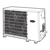
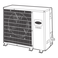
Outdoor Fan— A reinforced wire mount
holds the outdoor fan assembly in place.
Compressor Pressure Relief Valve —
Valve is located in compressor. Relief valve
opens at a pressure differential of approximately
450 ± 50 psig between suction (low side) and
discharge (high side) to allow pressure
equalization.
Internal Current and Temperature
Sensitive Overload—
Control resets
automatically when internal compressor motor
temperature drops to a safe level (overloads may
require up to 45 minutes to reset). When an
internal overload is suspected of being open,
check by using an ohmmeter or continuity tester.
If necessary, refer to Carrier Standard Systems
Techniques Manual, Chapter 2, for complete
information.
Pumpdown Procedure— The system
may be pumped down in order to make repairs
on low side without losing complete refrigerant
charge. To pumpdown:
1. Attach pressure gage to suction service valve
gage port.
2. Frontseat the liquid line valve.
CAUTION
The 38HDL unit coils hold only the factory-
designated amount of refrigerant. Additional
refrigerant may cause units to relieve pressure
through compressor internal pressure relief
valve (indicated by sudden rise of suction
pressure) before suction pressure reaches 5 psig.
If this occurs, shut off unit immediately, then
frontseat the suction valve and remove and
recover excess refrigerant following accepted
practice.
3. Start unit and run until suction pressure
reaches 5 psig.
4. Shut unit off and frontseat suction valve.
5. Depressurize low side of unit and recover
refrigerant following accepted practice.
Loss of Charge Pressure Switch —
This switch, mounted on the suction line, has
fixed non-adjustable settings. To check pressure
switch, attach pressure gage to suction service
valve gage port. Slowly close liquid shutoff
valve and allow compressor to pump down. Do
not allow compressor to pump down below 2
psig. Compressor should shut down when
suction pressure drops to cutout pressure in
Table 2, and should restart when pressure builds
up to cut-in pressure shown in Table 2.
High Pressure Switch —This switch,
mounted on the discharge line, has fixed non-
adjustable settings & auto reset. To check
pressure switch, attach pressure gauge to
MAXIMUM LINE LENGTHS
UNIT
MAXIMUM
EQUIVALENT
FT
MAXIMUM LIFT
— FAN COIL
BELOW
CONDENSING
UNIT
MAXIMUM LIFT
— FAN COIL
ABOVE
CONDENSING
UNIT
38HK 50 30* 30*
*Maximum distance permitted is 30 ft from lowest
system component to highest system component. For
longer line application please refer to appendix A.
 Loading...