38MHRC: Service Manual
Manufacturer reserves the right to change, at any time, specifications and designs without notice and without obligations.
5
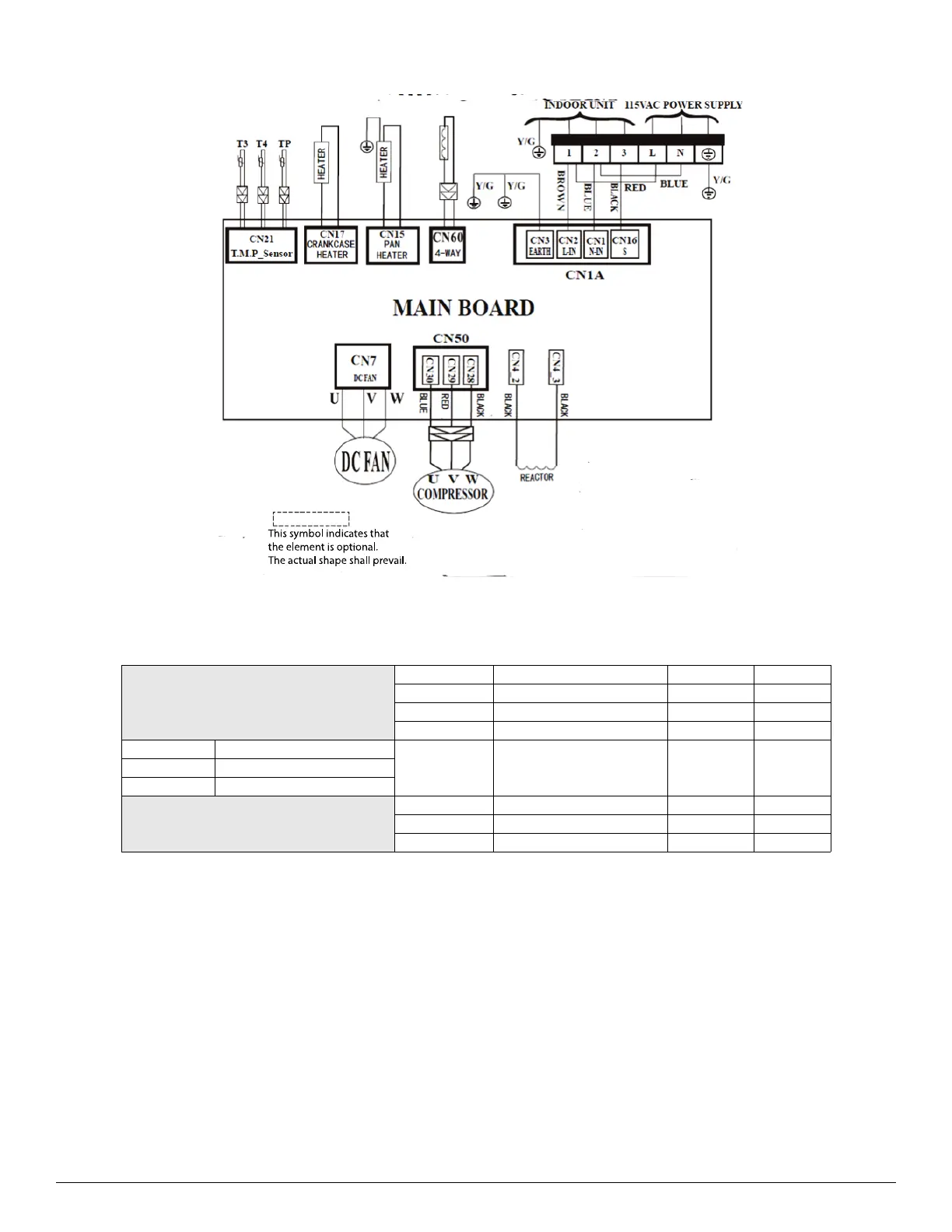
WIRING DIAGRAMS (HEAT PUMP)
A210450
Fig. 3 — Wiring Diagram Size 12K (115V)
Table 3 — Wiring Diagram Size 12K (115V)
CN1A
INPUT
115V
AC
CN4_2/4_3 INPUT 115V AC
CN7 OUTPUT 0-310V AC
CN60 OUTPUT 115V AC
T3 Condenser TEMP. Sensor
CN21 INPUT 0-5V DCT4 Ambient TEMP. Sensor
TP Discharge TEMP. Sensor
CN15 OUTPUT 115V AC
CN17 OUTPUT 115V AC
CN50 OUTPUT 0-310V AC

 Loading...