10 Specifications subject to change without notice. SG-38MPRA-02
Sizes 18K to 24K
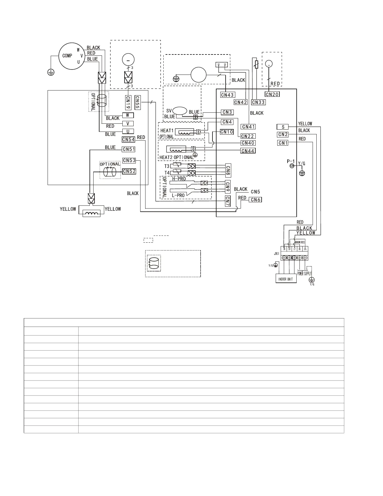
Fig. 7 — Wiring Diagram - Sizes 18K and 24K
Table 8 — Wiring Diagram - Sizes 18K and 24K
OUTDOOR UNIT MAIN BOARD
CODE PART NAME
CN1~CN2 Input:230VAC High voltage
CN5~CN6 Output:230VAC High voltage
P-1 Connection to the earth
CN10~CN44 Output:230VAC High voltage Basepan Heater
CN4~CN40 Output:230VAC High voltage Compressor Crankcase Heater
CN3~CN22 Output:230VAC High voltage
CN17~CN21 Output:Pin1-Pin4:Pulse waveform (0-12VDC), Pin5, Pin6(12VDC)
CN7 Output:Pin1(12VDC), Pin2(5VDC)Pin3(EARTH)
CN27~CN30 Output:Pin 2~Pin3(230VAC High voltage)
CN13 Pin1,Pin3,Pin5,Pin7,Pin9(5VDC):Pin2,Pin4,Pin6,Pin8,Pin10(0-5VDC)
CN33 Input:Pin1(0-5VDC),Pin2(5VDC), Discharge Temp
CN8 Input:Pin3,Pin4(5VDC),Pin2(0VDC),Pin1,Pin5(0-5VDC)
CN9 Input:Pin2,Pin4(0VDC),Pin1,Pin3(0-5VDC)H/L Pressure Switch
MAIN BOARD
Y/G
L
TP
EEV
FAN1
~
DRIVER BOARD
7
7
Applicable to the units
adopting AC motor only
CAP1
M
5(6)
5
4-WAY1
OPTIONAL
NOTE:Four-way valve
is used in the
Heat pump unit only
BLUE
Compressor crankcase heater
Basepan heater
FM1
Applicable to the units
adopting a DC motor only
Y/G
Notes:
This symbol indicates the element is optional,
the actual shape shall prevail.
NOTE:Use the magnetic ring
(not supplied, optional part)
to connect the connective cable
of the indoor and outdoor units
after installation. One magnetic
ring is used for one cable
.
L1
L2
BLUE(BLACK)
S
L1
L2
1L1L
L2