6
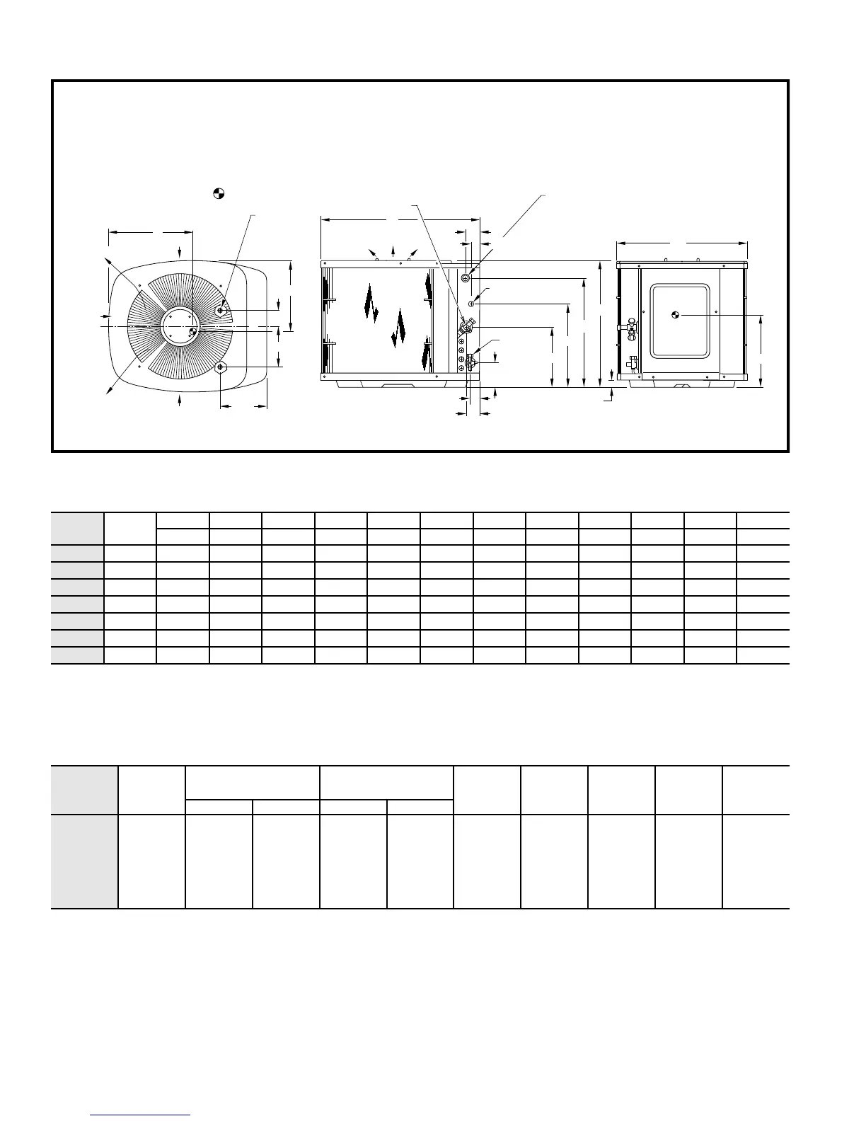
Dimensions
Electrical data
FLA
— Full Load Amps
NOTE:
Control circuit is 24v on all units and requires external power
HACR
— Heating, Air Conditioning, Refrigeration source.
LRA
— Locked Rotor Amps **The ampacity of non-metallic (NM) sheathed cable shall be that of
MCA
— Minimum Circuit Amps 60˚C (140˚F) conductors per NEC 1993, Article 336-26. If wire used
RLA
— Rated Load Amps is other than specified in chart, refer to applicable tables available in
* Permissible limits of the voltage range at which unit will operate satisfac- 1993 NEC. Copper wire must be used from disconnect to unit.
torily. Operation outside these limits may result in unit failure. All motors/compressors contain internal overload protection.
† Time-delay fuse.
‡ Length shown is as measured 1 way along the wire path between the
unit and the service panel for a voltage drop not to exceed 2%.
UNIT
SIZE SERIES
A B C D E F G H K L M N
In. In. In. In. In. In. In. In. In. In. In. In.
018
0, 1 25-7/8 22-1/2 27-1/2 2-13/16 6-15/16 15-1/2 21-7/8 5/8 12 13-3/4 9-3/4 2-3/8
024
0, 1 25-7/8 22-1/2 27-1/2 2-13/16 6-15/16 15-1/2 21-7/8 5/8 12 13-3/4 9-3/4 2-3/8
030
0, 1 25-7/8 30 34-15/16 4 9-3/4 15-1/2 21-7/8 3/4 15-1/8 17-1/4 13-1/8 2-15/16
036
0, 1 31-7/8 30 34-15/16 4 9-3/4 21-1/2 27-7/8 7/8 13-3/4 18 13 2-15/16
042
0, 1 25-7/8 30 34-15/16 4 9-3/4 15-1/2 21-7/8 7/8 16-1/2 18-3/4 13-3/8 2-15/16
048
0, 1 31-7/8 30 34-15/16 4 9-3/4 21-1/2 27-7/8 7/8 14-1/8 19 14 2-15/16
060
0, 1 37-7/8 30 34-15/16 4 9-3/4 27-1/2 33-7/8 7/8 14-1/8 19-1/2 15-1/2 2-15/16
OUTDOOR
UNIT
V/PH
60 Hz
OPER VOLTS* COMPR
FAN FLA MCA
MIN WIRE
SIZE**
60˚C/75˚C
MAX
LENGTH
(Ft)‡ 60C/
75C
MAX FUSE†
OR HACR
TYPE CKT
BKR AMPSMax Min LRA RLA
018-30
018-31
024-30, 31
030-30, 31
036-30, 31
042-30, 31
048-30, 31
060-30, 31
208/230/1 253 187
50.0
49.0
62.5
90.5
107.0
107.0
129.0
169.0
9.9
8.9
11.5
17.9
20.7
22.8
28.7
31.1
0.8
0.8
0.8
0.9
1.4
1.4
1.4
1.4
13.3
11.9
15.3
23.3
27.3
29.9
37.3
40.3
14/14
14/14
14/14
12/12
10/10
10/10
8/8
6/8
61/58
65/60
53/50
55/52
74/70
67/63
84/80
160/90
20
20
25
40
40
50
60
60
C
2
1
/2
"
1
9
/16
"
AIR DISCHARGE
N
4
3
/16
"
3
/8 IN.
DIA.
LIQUID LINE
CONN
1
3
/4
"
FIELD POWER SUPPLY CONN
7
/8 IN.
DIA HOLE WITH
1
1
/8 IN. DIA KNOCKOUT
AND
1
3
/8 IN. DIA KNOCKOUT
10
1
/2
"
F
G
A
FIELD CONTROL SUPPLY
CONN
7
/8 IN.
DIA HOLE
8
3
/16
"
AIR DISCHARGE
AIR DISCHARGE
AIR IN
AIR IN
AIR IN
H DIA SERVICE LINE CONN
3
/8 IN.
DIA TIEDOWN
KNOCKOUTS (2)
PLACES
B
1
1
/4
"
M
ACCESS
PANEL
L
K
D
E
C
L
1. Allow 30 in.
clearance to service side of unit, 48 in. above unit, 6 in.
on one side, 12 in. on remaining side, and 24 in. between units for proper airflow.
Minimum outdoor operating ambient in cooling mode is 55°F (unless low ambient control is used) max 125°F.2.
Maximum outdoor operating ambient in heating mode is 66°F.3.
Series designation is the 13th position of the unit model number.5.
Center of gravity .6.
NOTES:
 Loading...