40FKA
Comfort Heat Pump System
002-006
Installation Instructions
NOTE: Read entire manual before starting installation.
This symbol → indicates a change from the last publication.
See Back Page for QUICK REFERENCE COMFORT HEAT
SET-UP INSTRUCTIONS.
SAFETY CONSIDERATIONS
Improper installation, adjustment, alteration, service, maintenance,
or use can cause explosion, fire, electrical shock or other condi-
tions which may cause personal injury or property damage.
Consult a qualified installer, service agency, or your distributor or
branch for information or assistance. The qualified installer or
agency must use factory-authorized kits or accessories when
modifying this product. Refer to the individual instructions pack-
aged with the kits or accessories when installing.
Follow all safety codes. Wear safety glasses and work gloves. Use
quenching cloth for brazing operations. Have fire extinguisher
available. Read these instructions thoroughly and follow all
warnings or cautions attached to the unit and in installation
instructions or manuals. Consult local building codes and National
Electrical Code (NEC) for special requirements.
Recognize safety information. This is the safety-alert symbol
.
When you see this symbol on the unit and in instructions or
manuals, be alert to the potential for personal injury.
Understand the signal words DANGER, WARNING, and CAU-
TION. These words are used with the safety-alert symbol. DAN-
GER identifies the most serious hazards which will result in severe
personal injury or death. WARNING signifies hazards which
could result in personal injury or death. CAUTION is used to
identify unsafe practices which would result in minor personal
injury or product and property damage. NOTE is used to highlight
suggestions which will result in enhanced installation, reliability,
or operation.
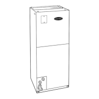
Fig. 1—Comfort Heat Pump System
A98049
40FKA FAN COIL
THERMIDISTAT ™
CONTROL
OUTDOOR TEMPERATURE SENSOR
Visit www.carrier.com
Manufacturer reserves the right to discontinue, or change at any time, specifications or designs without notice and without incurring obligations.
Book 1 4
Tab 3d 2e
PC 101 Catalog No. 534-011 Printed in U.S.A. Form 40FK-5SI Pg 1 7-00 Replaces: 40FK-3SI