30
Maintenance and service
ATTENTION:
Before performing any service or
maintenance operations, turn OFF the
main power switch.
In order to obtain maximum performance,
special attention should be paid to the
following points:
• Inspect and clean the outdoor unit,
especially the heat exchanger coil.
• Ensure that all rubber and insulating
joints are in good condition.
• Check and clean condenser drain pan of
the indoor unit; the same check must be
made for the heat pump outdoor units.
• Check tightness of electric connections.
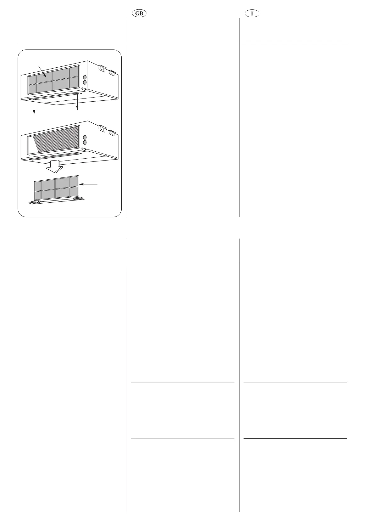
• Clean or replace the air filter of the indoor
unit.
Air filter.
Manutenzione e cura
ATTENZIONE:
Prima di iniziare qualunque operazione
di pulizia o di manutenzione togliere
l’alimentazione elettrica.
Per ottenere ottime prestazioni, si consiglia
di prestare particolare attenzione ai
seguenti punti:
• Ispezionare e pulire l'unità esterna ed in
particolare la batteria di scambio
termico.
• Assicurarsi che i giunti in gomma e
isolanti siano in buone condizioni.
• pulire e liberare da eventuali ostruzioni la
bacinella e lo scarico della condensa
dell'unità interna; eseguire gli stessi
controlli sulle unità esterne a pompa di
calore.
• controllare il serraggio dei contatti
elettrici.
• pulire o sostituire il filtro dell'aria dell'uni-
tà interna.
Filtro aria.
Troubleshooting chart
Alarm code
Code Description
2 Indoor unit air sensor
3 Indoor unit coil sensor
4 Outdoor unit coil sensor
6 Outdoor unit in alarm mode
7 Condensation pump /
Condensation level
Example:
Outdoor unit coil sensor not connected or
not operating.
The alarm code (3) is deduced from the
number of times the green LED flashes, at
intervals of 5 seconds, blocking unit
operation.
A series of possible faults is related below,
as well as the probable causes and
suggested solutions.
However, in the event of a unit malfunction,
it is advisable to disconnect the power
supply and ascertain the cause.
Symptoms / Cause / R
EMEDY
Unit does not start
• No power supply: C
HECK
• Main switch open: CLOSE SWITCH
• Current wires cut: REPAIR OR REPLACE
• Fuses blown:
R
EPLACE AND CHECK CONSUMPTIONS
• Protector tripped: RESET AS DESCRIBED
• Thermostat wrongly adjusted:
S
ELECT A MORE SUITABLE TEMPERATURE
Ricerca inconvenienti
Codice di allarme
Codice Descrizione
2 Sensore aria unità interna
3 Sensore batteria unità interna
4 Sensore batteria unità esterna
6 Unità esterna in allarme
7 Pompa condensa / livello
condensa
Esempio:
Sensore batteria unità interna non collega-
ta o non funzionante.
Il codice di allarme (3) si deduce dalle volte
che il led verde lampeggia, ad intervalli di 5
secondi, bloccando il funzionamento
dell'unità.
Di seguito sono nominati alcuni inconve-
nienti possibili, con la causa probabile e la
soluzione suggerita.
In ogni caso è consigliabile togliere
l’alimentazione e accertare la causa.
Anomalia / Causa / R
IMEDIO
L'unità non funziona
• Mancanza di alimentazione elettrica: V
ERIFICARE
• Interruttore principale aperto: C
HIUDERE
L
’
INTERRUTTORE
• Cavi della corrente tagliati: R
IPARARE
O
SOSTITUIRE
• Fusibili bruciati:
S
OSTITUIRE
E
VERIFICARE
GLI
ASSORBIMENTI
• Una protezione è intervenuta: R
ISTABILIRE
COME
DESCRITTO
• Termostato regolato erroneamente
S
ELEZIONARE
UNA
TEMPERATURA
PIÙ
ADEGUATA


 To Next Page