4 Specifications subject to change without notice. 40MAHB-01SI
PARTS
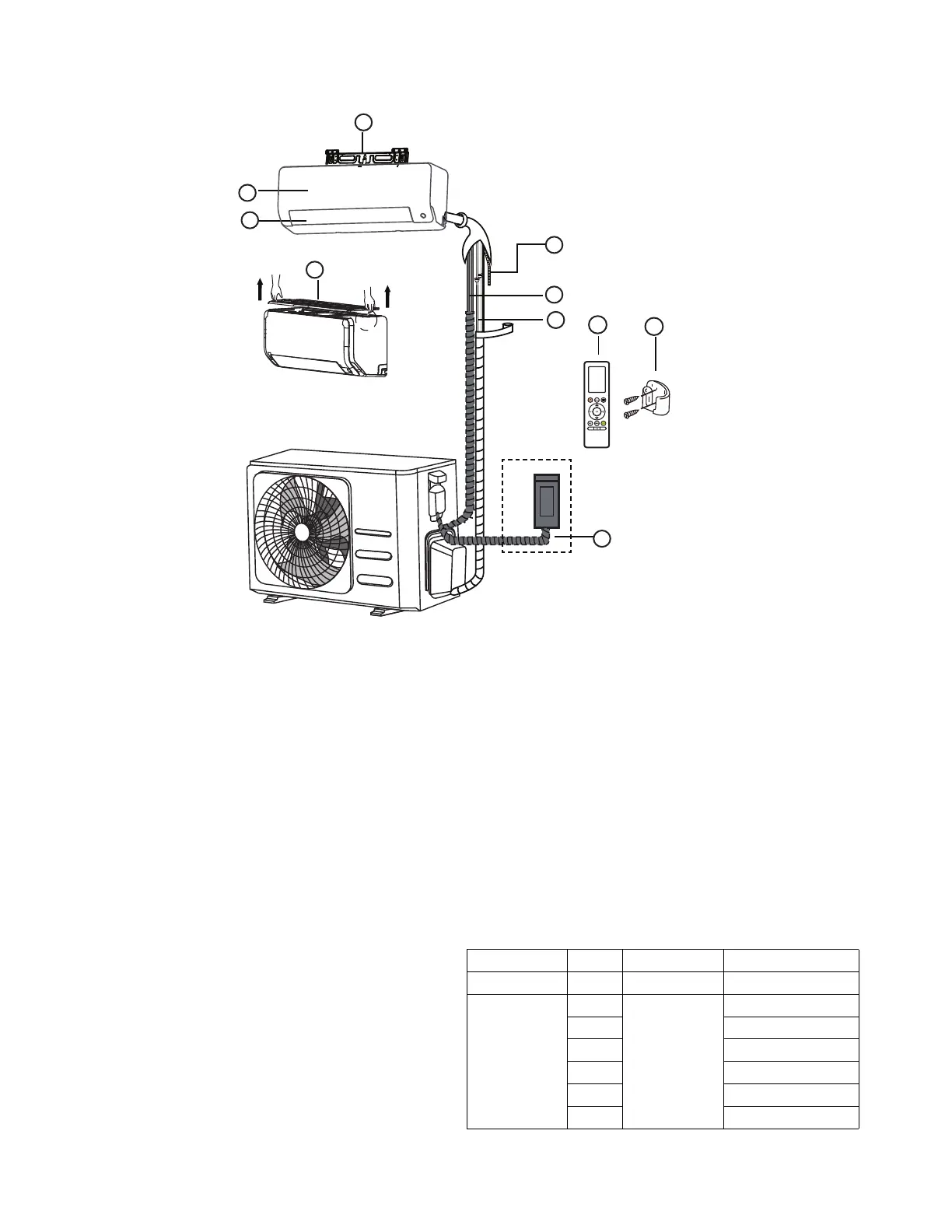
Fig. 2 — Parts
NOTE: Illustrations in this manual are for reference only. The actual shape of the indoor unit and parts may differ slightly.
1. Wall Mounting Plate
2. Front Panel
3. Louver
4. Air Filter
5. Drainage Pipe
6. Signal Cable
7. Refrigerant Piping
8. Remote Controller
9. Remote Controller Holder (some units)
10. Outdoor Unit Power Cable (some units)
NOTES:
- If the outdoor unit is higher than the indoor unit, prevent
rain from flowing into the indoor unit along the
connection pipe by making a inverted trap in the
connection pipe before it enters the wall to the indoor
unit. This ensures that rain drips from the connection
pipe before it enters the wall.
- Piping and the interconnecting wiring are field supplied.
- The illustration above (Fig. 2) is only a sketch. Different
models may be differ slightly.
The units listed in Table 3 are addressed in these installation
instructions.
Table 3 — Indoor Units
DESCRIPTION BTUH V-PH-HZ ID MODEL NO.
12 115-1-60 40MAHBQ12XA1
HIGH WALL
HEAT PUMP
9
208/230-1-60
40MAHBQ09XA3
12 40MAHBQ12XA3
18 40MAHBQ18XA3
24 40MAHBQ24XA3
30 40MAHBQ30XA3
36 40MAHBQ36XA3
 Loading...