7
OUTDOOR UNIT INSTALLATION
1. Use a rigid base to support unit in a level position.
NOTE: For applications requiring cooling with outdoor
temperatures below 55_F(13_C), a low ambient control
field--installed accessory is available. Consult the Installation
Instruction for the low ambient kit for further information.
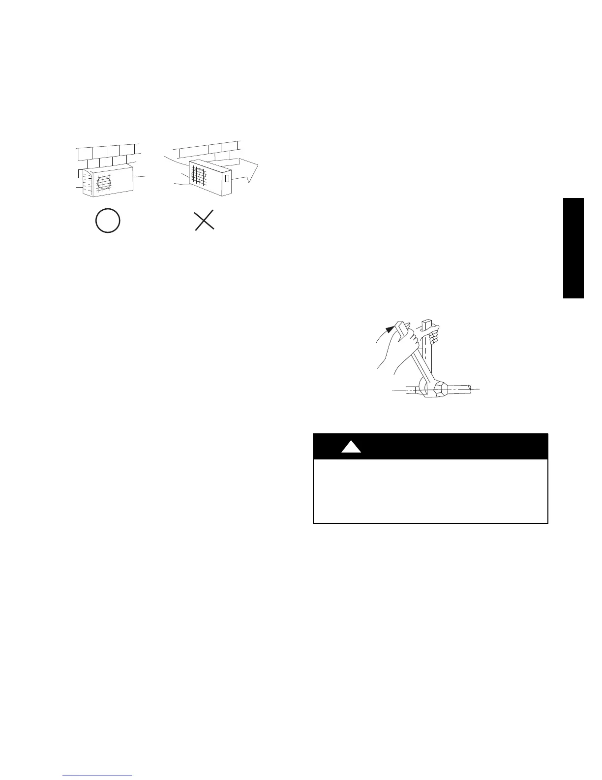
If the installation location may be exposed to strong wind , use a
wind baffle. Check with your Carrier representative to obtain
drawings for wind baffles.
Strong
wind
A07350
Fig. 10 --- High Wind Installation
2. Locate outdoor unit and connect piping and wiring.
MAKE REFRIGERANT PIPING CONNECTIONS
(OUTDOOR UNIT)
IMPORTANT: Use refrigeration grade tubing ONLY. No
other type of tubing may be used. Use of other types of tubing
will void manufacturer’s warranty.
Do not open service valves or remove protective caps from tubing
ends until all the connections are made.
Bend tubing with bending tools to avoid kinks and flat spots.
Keep the tubing free of dirt, sand, moisture, and other
contaminants to avoid damaging the refrigerant system.
Avoid sags in the suction line to prevent the formation of oil traps.
Insulate each tube with minimum 3/8--in. (10 mm) wall thermal
pipe insulation. Inserting the tubing into the insulation before
making the connections will save time and improve installation
quality.
1. Remove service valve cover if provided with unit.
2. Cut tubing with tubing cutter. Remove service connection
if provided with unit.
3. Install correct size flare nut onto tubing and make flare con-
nection.
4. Apply a small amount of refrigerant oil to the flare connec-
tion on the tubing.
5. Properly align tubing in with service valve.
6. Tighten flare nut and finish installation using two wrenches
as shown in Fig. 11.
A07354
Fig. 11 --- Tighten Flare Nut
CAUTION
!
EQUIPMENT DAMAGE HAZARD
Failure to follow this caution may result in equipment
damage or improper operation.
Excessive torque can break flare nut depending on
installation conditions.
38/40MVC, MVQ
 Loading...