4.1.5.- Retirar tapa caja eléctrica auxiliar, o de la
caja eléctrica de la unidad, según modelos.
4.1.6.- Fijar mangueras
Manguera A, formada por:
• Sensor de impulsión (BT7)
• Cables 35 y 36.
Manguera B, formada por:
• Cables 80, 81, 84, 85, 86, 87, 90, 91, 93, 94, 95, 96,
111, 112, 113 y tierra.
ATENCIÓN
En unidades partidas, es necesario reemplazar la
Manguera B, por otra fabricada por el instalador de lon-
gitud apropiada, manteniendo el mismo número de ca-
bles y la numeración de éstos.
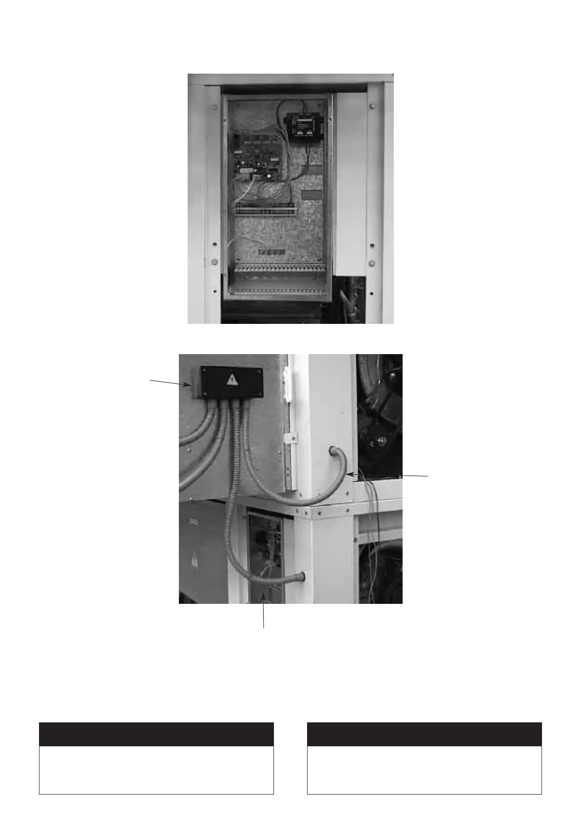
4.1.5.- Remove the cover on either the auxiliary
electrical cabinet or the unit's electrical
cabinet, depending on the model.
4.1.6.- Attach hoses
Hose A consists of:
• Out-flow sensor (BT7)
• Cables 35 and 36.
Hose B consists of:
• Cables 80, 81, 84, 85, 86, 87, 90, 91, 93, 94, 95, 96,
111, 112, 113 and earth.
ATTENTION
In split units, Hose B must be replaced by another
one, manufactured by the installer, which must be of the
appropriate length, and maintain the same number of ca-
bles and numbering.
14
Caja de conexiones X2
Junction box X2
A
B
 Loading...