EasyManua.ls Logo

Carrier 40VAM-C8FATEE - User Manual

Carrier 40VAM-C8FATEE
48 pages
Print Icon
To Next Page IconTo Next Page
Loading...
Installation
Manual
VRF DX COIL INTERFACE
MODEL NAME
Dx-coil controller
40VAM--C8FATEE
(Terminal block without relay)
40VAMR-C8FATEE
(Terminal block with relay)
Dx-valve kit
40VA010V8-ATEE
40VA020V8-ATEE
For commercial use
1135451001
English
Notice: is committed to continuously improving its products to ensure the highest quality and
reliability standards, and to meet local regulations and market requirements. All features and specications
are subject to change without prior notice.
00_1135451001 Cover.indd 100_1135451001 Cover.indd 1 4/7/2566 BE 09:254/7/2566 BE 09:25
Question and Answer IconNeed help?

Do you have a question about the Carrier 40VAM-C8FATEE and is the answer not in the manual?

Overview

This document describes the installation and operation of the Carrier VRF DX Coil Interface, which connects an Air Handling Unit (AHU) with a Direct Expansion (DX) coil to a Carrier VRF outdoor unit. The interface is designed for commercial use and utilizes R410A refrigerant.

General Precautions and Safety

Installation, maintenance, repair, and removal of the VRF DX Coil Interface must only be performed by a qualified installer or service person. Failure to adhere to proper procedures can lead to fire, electric shock, injury, water leakage, noise, or malfunction. Always wear protective gloves and safety work clothing. When working at heights, use a ladder compliant with ISO 14122 and wear a helmet. Before any work, disconnect all remote electric power supplies and set the circuit breaker to the OFF position, placing a "Work in progress" sign. The refrigerant used is R410A, which operates at higher pressures than R22, requiring specific pipes and tools. Do not modify or disassemble the product, and ensure it is transported in a stable condition.

Installation Location

The DX Coil Interface should be installed indoors, protected from rain, wind, and direct sunlight. Avoid locations with high-frequency generating machinery, oil mist, dense vapor, salt, acidic or alkaline atmospheres, or sulfurizing gas. Do not place water-containing vessels near the unit to prevent electric shock from spills. Ensure the AHU has an air filter to prevent dust accumulation and potential water leakage or defrosting issues. Maintain a minimum 1-meter separation from televisions, radios, or remote controllers to prevent interference. The unit is not intended for special-purpose use (e.g., food, animals, precision machinery, artwork storage) or locations where wetness could cause damage. Avoid areas with organic solvents or high humidity, as condensation may occur. If installed in high-humidity areas (dew-point temperature 23°C or higher), additional heat insulation (e.g., grass wool) should be applied to all contact points. Ensure sufficient space for service and fix the DX Coil Controller and DX Valve Kit to a stable surface to prevent vibration or noise. Do not install in locations with significant temperature differences or high temperatures/humidity (52°C or more / RH 80% or more) to prevent condensation, rust, or malfunction. Avoid installing where iron or metal dust is present, as it can lead to spontaneous combustion.

Refrigerant Piping

Install refrigerant pipes securely before operating the air conditioner. Operating the compressor with an open valve and no refrigerant pipe can lead to air intake, over-pressurization, and injury. After installation, confirm no refrigerant gas leaks. If R410A leaks and comes into contact with a fire source, noxious gases may be generated. Purge air completely from the refrigerating cycle after installation or relocation to prevent malfunction. Use nitrogen gas for airtightness tests and ensure charge hoses are not slack.

Electrical Wiring

Electrical work must be performed by a qualified installer or service person. Wear protective gloves, insulating shoes, and clothing to prevent electric shocks. Use wiring that meets specifications in the Installation Manual and local regulations to prevent electric shocks, leakage, smoking, or fire. Connect earth wires properly; do not connect them to gas pipes, water pipes, lightning conductors, or telephone earth wires. Install an easily accessible circuit breaker that meets specifications and local regulations. For outdoor installations, use an outdoor-rated circuit breaker. Do not extend power wires, as this can cause smoking or fire. Electrical wiring must conform to local laws and regulations. Ensure the circuit breaker is attached and use fuses of the correct capacity. The power supply must match the rated voltage and use a dedicated circuit for the DX Coil Interface.

Test Run

Before operating the air conditioner, ensure the electrical control box cover of the AHU and the outdoor unit service panel are closed. Set the circuit breaker to ON. Check insulation resistance (1 MΩ or more) between the charge section and non-charge metal section. If resistance is low, do not operate the unit. Verify that the outdoor unit valve is fully open. To protect the compressor, allow 12 hours of power-ON before operation. Do not forcibly perform a test run by pressing the electromagnetic contactor, as protective devices will not function. Perform cooling/heating test runs to ensure satisfactory system operation.

System Configuration

The VRF DX Coil Interface connects to New Carrier band VRF systems. Each cycle requires one outdoor unit and one DX Coil Interface. AHU design should refer to the AHU submittal.

  • TA type: Connects 3rd party indoor units or AHUs as VRF indoor units, controlling return air temperature via a remote controller. Primarily for room temperature conditioning.
  • TF type: Controls capacity by setting the discharge temperature via a remote controller. Primarily for ventilation.
  • DDC type: Direct capacity control of Carrier VRF outdoor units via analogue input (0-10 V). Mainly for discharge air temperature control in linked AHU systems.

DX Coil Interface Models and Capacity

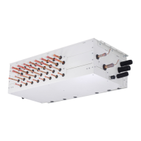
The DX Coil Interface includes a DX-coil controller (40VAM--C8FATEE without relay, 40VAMR-C8FATEE with relay) and DX-valve kits (40VA010V8-ATEE, 40VA020V8-ATEE).

  • Normal configuration: Supports DX coil capacities from 8 HP to 40 HP, typically with one DX-coil controller and one or two DX-valve kits.
  • Interlaced/Split face configuration: Supports DX coil capacities from 16 HP to 120 HP, using multiple DX-coil controllers and DX-valve kits. This configuration allows for 2 or 3 inlet & outlet ports, arranged up and down, interlaced, or in parallel rows.

Accessories

The DX-coil controller includes:

  • TA sensor (7.5 m, yellow connector)
  • TC1 sensor (7.5 m, brown connector)
  • TC2 sensor (7.5 m, black connector)
  • TCJ sensor (7.5 m, red connector)
  • TF sensor (7.5 m, green connector)
  • Sensor holder (TC1, O.D. 6.35 mm, length 26 mm)
  • Sensor clip (TC1)
  • Sensor holder (TC2, TCJ, O.D. 8 mm, length 26 mm)
  • Sensor clip (TC2, TCJ)

The DX-valve kit includes:

  • Sensor holder (TC1, O.D. 6.35 mm, length 26 mm)
  • Sensor clip (TC1)
  • Sensor holder (TC2, TCJ, O.D. 8 mm, length 26 mm)
  • Sensor clip (TC2, TCJ)
  • Heat insulation (O.D. 40 mm, length 210 mm)
  • Cable tie (length 152 mm)

Note: Sensor holders for TA and TF sensors are not included as accessories.

Sensor Installation

  • TC1 sensor: Install in the collecting part of the gas header, on the lower side (45°) to detect stable temperature.
  • TC2 sensor: Install between the liquid pipe distributor and the PMV (attached to the AHU's refrigerant cycle).
  • TCJ sensor: Install in the pass where the capillary tube temperature is lowest, 50 mm ± 25 mm from the end plate.
  • TA/TF sensor: Install where airflow is best. The TA sensor must be in the return air position, prior to mixing with fresh air. The TF sensor should be in a place where discharge air temperature is uniform.
  • If sensors are exposed to thermal effects, cover them with heat insulator material and fix with a fixing band. Protect lead wires from external force, heat, and water.

Piping Size and Y-joint

Maximum real piping length between the valve kit and DX coil is 5 meters. Y-joints (A, B) are specified based on DX coil HP (e.g., RBM-BY205E for 24 HP, RBM-BY305E for 26-60 HP, RBM-BY405E for 61.2 HP or more).

Electrical Connection and Wiring

The DX-coil controller requires an exclusive power supply (220-240 V~, 50 Hz or 208-230 V~, 60 Hz) with a 3-core, 2.5 mm² cable. The power supply switch, earth leakage breaker, and fuse rating should be selected based on the accumulated total current values of the DX-coil controllers. Control wiring between indoor/outdoor units and central controllers uses 2-core shielded wires (0.5 mm² to 2.0 mm², up to 500 m). RS-485 communication cables use 2-core shielded wires (1.25 mm², up to 500 m). Do not run communication and power wires in parallel or in the same conduits to prevent noise.

Terminal Functions

  • L(1), N(2), (3): Power supply input. Requires a switch with at least 3 mm contact separation.
  • Uv(U1), Uv(U2): Communication line between DX-coil controller and outdoor units.
  • *AB, AB: Remote controller wiring. An optional wired remote controller can be attached for installation, maintenance, and group control.
  • *DO1-DO6 (Digital Outputs): Provide various digital output signals (DC12 V) such as operating output, alarm active, fan motor active, defrost mode, user-defined outputs, thermostat ON, cooling/heating start-up, pre-defrost, cooling OPEN/heating CLOSE, notice code, and fan speed outputs (high, medium, low). Output functions can be selected using rotary switches SW503 and SW504.
  • *DI1-DI6 (Digital Inputs): Provide digital input signals (DC12 V or no voltage, or DC5 V for DI6) for safety contact, external trouble, forced thermostat OFF, notice code, operation mode (cool/heat), and external ON/OFF. DI1 can be configured for normally closed or normally open contacts, with check code P10 generated if the contact state changes for more than 1 minute.
  • AI1, AI2 (Analogue Inputs 4-20 mA): Used for FAN interlocking control by external input. FAN mode switching threshold values can be changed via DN settings.
  • AI3, AI4 (Analogue Inputs 0-10 V): Used for analogue input capacity control. Can operate with STEPPED or LINEAR response, selected via SW501 Bit4. Also used for set temperature changes in TA/TF types.
  • AO1, AO2 (Analogue Outputs 0-10 V): Used for FAN speed output. Output voltage can be changed via DN settings.
  • R, BL, OR, Y, W (PMV 1/PMV 2): Connects to the PMV cable. Match wiring colors. PMV cable cannot be extended beyond 5 m.
  • MdG, MdA/MdB (Modbus G, Modbus A/Modbus B): Modbus communication terminals.

Modbus Setting

Modbus communication is available. Set the baud rate using SW506, address using SW507 (up to 16 addresses), and terminating resistor using SW801 (120 ohm for the unit with the latest address, OFF for others). Function codes include read holding register, read input register, write single holding register, diagnostics, get comm. event counter, get comm. event log, and write multiple holding registers.

DN Setting

Before making DN settings, ensure the air conditioner is stopped. Only set Code Nos. listed in the manual to avoid malfunction.

  1. Press and hold the menu button and [▽] setting button simultaneously for 10 seconds or more. "ALL" will flash, then display indoor unit numbers.
  2. Use [▽][△] to select the indoor unit for settings. The fan of the selected unit will run, and louvers will swing.
  3. Press the OFF timer button to confirm the selected unit.
  4. Press the menu button to flash the Code No. Use [▽][△] to change it.
  5. Press the menu button to flash the Set data. Use [▽][△] to change it.
  6. Press the OFF timer button to complete the setup. Repeat from Procedure 4 for other settings.
  7. When all settings are complete, press the ON/OFF button to return to normal mode. "SETTING" will flash, then disappear.

Troubleshooting

If a problem occurs, the OFF timer indicator will alternately show a check code and the indoor unit number. To check troubleshooting history (up to 4 incidents):

  1. Press the OFF timer button for over 10 seconds. The display will show "Service check" and then "01" (newest incident) in the temperature indicator, with the check code and indoor unit number alternating on the OFF timer indicator.
  2. Press the setting button to view recorded incidents in sequence (01 to 04).
  3. After checking, press the ON/OFF button to return to regular mode. If the unit is operating, press ON/OFF again to stop it.

Common Check Codes:

  • E01: No master remote controller, faulty communication. Check remote controller setup and inter-unit tie cable.
  • E09: Duplicated master remote controller. Check remote controller setup and inter-unit tie cable.
  • F01, F02, F03: TCJ, TC2, TC1 sensor trouble. Check connections, wiring, resistance characteristics, P.C. board, and sensor installation.
  • F10, F11: TA, TF sensor trouble. Check connections, wiring, resistance characteristics, and P.C. board.
  • L02: Outdoor units model disagreement. Check outdoor unit model and compatibility with DX-coil interface.
  • L09: Indoor unit Capacity Code incorrect. Check DN Code 11 settings.
  • L22: Incompatible group combination of indoor units. Check indoor unit model names and P.C. board.
  • L30: External trouble. Check fan operation monitoring at DI2/*DI2. "CLOSED" contact generates L30.
  • P10: Safety contact trouble. Check contact at DI1/*DI1. "OPEN" contact generates P10. If not used, install a bridge connection.

For other check codes, refer to the service manual.

Carrier 40VAM-C8FATEE Specifications

General IconGeneral
BrandCarrier
Model40VAM-C8FATEE
CategoryController
LanguageEnglish

Related product manuals