Do you have a question about the Carrier XCT7 40VCW117FQEE and is the answer not in the manual?
Confirms product conformity with EU directives like Machinery and EMC.
Ensures restriction of hazardous substances in electrical and electronic equipment.
Informs consumers about the proper disposal of electrical and electronic products.
Details proper disposal procedures for the air conditioning system and its components.
Specifies R410A refrigerant type and its Global Warming Potential (GWP) value.
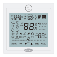
Describes the layout and components of the controller's display.
Explains the meaning of various symbols and icons shown on the controller.
Details master/slave wired controller setup and fan speed indicators.
Describes the indicators for Auto, Cool, Heat, and Fan operating modes.
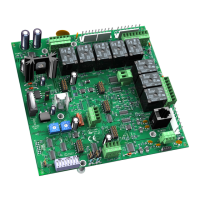
Defines the functions and default settings for dip switches SWI and SW2.
Covers system initialization display and audible alert functions.
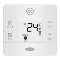
Explains how to cycle through and select operating modes using the MODE button.
Details how to select fan speeds using the FAN button and associated icons.
Describes how to use TEMP+ and TEMP- keys for precise temperature adjustments.
Instructions on entering the special function menu via button combination.
Explains adjustment of horizontal and vertical louvers and saving settings.
Describes the clean filter alert function and how to reset it.
Details ECO mode, HRV, and vacation mode settings.
Explains how to lock louvers in specific positions for cooling or heating.
Guides on setting ECO parameters for cooling, heating, and dehumidification.
Details the procedure to activate and deactivate the Child Lock function.
Explains the central control lock and its availability with central systems.
Provides instructions for converting temperature display between Fahrenheit and Celsius.
Explains how to adjust the ambient temperature reading for accurate control.
Details how to activate Forced Defrost, Cooling, and Heating modes.
Guides on how to check for system errors and review past error codes.
Describes mode lock functionality and setting allowed mode combinations.
Explains how to check indoor unit parameters and addresses.
Wiring diagrams for using one controller to manage up to 16 indoor units.
Wiring setup for a single wire controller connected to one indoor unit.
Wiring configuration for connecting two wire controllers to a single indoor unit.
Details required wire types and lengths for communication wiring.
Visual representation of the controller's wiring connections.
Step-by-step guide for installing the wired controller onto the wall.
| Model | XCT7 40VCW117FQEE |
|---|---|
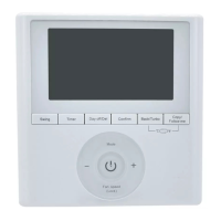
| Display | Touchscreen |
| Power Source | 24V AC |
| Humidity Control | Yes |
| Filter Change Alert | Yes |
| Programming | Programmable |
| Connectivity | Wi-Fi |