EasyManua.ls Logo

Carrier A Series - User Manual

Carrier A Series
50 pages
To Next Page IconTo Next Page
Loading...
Installation, Start-up, Operating and
Service and Maintenance Instructions
SAFETY CONSIDERATIONS . . . . . . . . . . . . . . . . . . . . . . . . . . . . . 3
INTRODUCTION . . . . . . . . . . . . . . . . . . . . . . . . . . . . . . . . . . . . . . . 4
CODES AND STANDARDS . . . . . . . . . . . . . . . . . . . . . . . . . . . . 4
ELECTROSTATIC DISCHARGE (ESD) PRECAUTIONS PROCE-
DURE. . . . . . . . . . . . . . . . . . . . . . . . . . . . . . . . . . . . . . . . . . . . . . . 5
LOCATION . . . . . . . . . . . . . . . . . . . . . . . . . . . . . . . . . . . . . . . . . . . . 6
GENERAL . . . . . . . . . . . . . . . . . . . . . . . . . . . . . . . . . . . . . . . . . . . 6
AIR FOR COMBUSTION AND VENTILATION . . . . . . . . . . . . 6
Table 1 – Minimum Free Area Required for Each Combustion Air
opening of Duct to Outdoors . . . . . . . . . . . . . . . . . . . . . . . . . . . . . 7
Table 2 – Minimum Space Volumes for 100% Combustion, Ventila-
tion, and Dilution from Indoors . . . . . . . . . . . . . . . . . . . . . . . . . . . 8
INSTALLATION . . . . . . . . . . . . . . . . . . . . . . . . . . . . . . . . . . . . . . . . 9
UPFLOW INSTALLATION . . . . . . . . . . . . . . . . . . . . . . . . . . . . . 9
DOWNFLOW INSTALLATION . . . . . . . . . . . . . . . . . . . . . . . . . 9
Table 3 – Opening Dimensions - In. (mm) . . . . . . . . . . . . . . . . . 10
HORIZONTAL INSTALLATION . . . . . . . . . . . . . . . . . . . . . . . 10
LOCATION RELATIVE TO COOLING EQUIPMENT . . . . . . 11
AIR DUCTS . . . . . . . . . . . . . . . . . . . . . . . . . . . . . . . . . . . . . . . . . . . 12
GENERAL REQUIREMENTS . . . . . . . . . . . . . . . . . . . . . . . . . . 12
SUPPLY AIR CONNECTIONS . . . . . . . . . . . . . . . . . . . . . . . . . 12
RETURN AIR CONNECTIONS. . . . . . . . . . . . . . . . . . . . . . . . . 12
Table 4 – Air Delivery - CFM (With Filter)* . . . . . . . . . . . . . . . 13
GAS PIPING. . . . . . . . . . . . . . . . . . . . . . . . . . . . . . . . . . . . . . . . . . . 19
Table 5 – Maximum Capacity of Pipe . . . . . . . . . . . . . . . . . . . . . 19
ELECTRICAL CONNECTIONS. . . . . . . . . . . . . . . . . . . . . . . . . . . 20
Table 6 – Electrical Data . . . . . . . . . . . . . . . . . . . . . . . . . . . . . . . 21
J-BOX RELOCATION . . . . . . . . . . . . . . . . . . . . . . . . . . . . . . . . 21
NOTES FOR FIGURES 28 - FIGURES 35: . . . . . . . . . . . . . . . . . . 24
ACCESSORIES . . . . . . . . . . . . . . . . . . . . . . . . . . . . . . . . . . . . . . 25
VENTING. . . . . . . . . . . . . . . . . . . . . . . . . . . . . . . . . . . . . . . . . . . . . 25
GENERAL VENTING REQUIREMENTS . . . . . . . . . . . . . . . . 25
Table 7 – Combined Appliance Maximum Input Rating
in Thousands of Btuh per Hour . . . . . . . . . . . . . . . . . . . . . . . . . . 27
Table 8 – Minimum Allowable Input Rating of
Space-Heating Appliance in Thousands of Btuh per Hour . . . . . 27
START-UP, ADJUSTMENT, AND SAFETY CHECK . . . . . . . . . 31
GENERAL . . . . . . . . . . . . . . . . . . . . . . . . . . . . . . . . . . . . . . . . . . 31
START-UP PROCEDURES . . . . . . . . . . . . . . . . . . . . . . . . . . . . 31
ADJUSTMENTS . . . . . . . . . . . . . . . . . . . . . . . . . . . . . . . . . . . . . 32
Table 9 – Altitude Derate Multiplier for U.S.A. . . . . . . . . . . . . . 32
Table 10 – Blower Off Delay Setup Switch . . . . . . . . . . . . . . . . 34
Table 11 – Gas Rate (CU ft./hr). . . . . . . . . . . . . . . . . . . . . . . . . . 34
Table 12 Orifice Size and Manifold Pressure (In. W.C.) for Gas Input
Rate (Tabulated Data Based on 22,000 Btuh High-Heat/14,500 Btuh
for Low-Heat per Burner, Derated 4 Percent for Each 1000 Ft.(305 M)
Above Sea Level). . . . . . . . . . . . . . . . . . . . . . . . . . . . . . . . . . . . . 35
SERVICE AND MAINTENANCE
PROCEDURES . . . . . . . . . . . . . . . . . . . . . . . . . . . . . . . . . . . . . . . . 38
GENERAL. . . . . . . . . . . . . . . . . . . . . . . . . . . . . . . . . . . . . . . . . . 38
CARE AND MAINTENANCE. . . . . . . . . . . . . . . . . . . . . . . . . . 39
Table 13 – Filter Size Information - In. (mm) . . . . . . . . . . . . . . . 40
SEQUENCE OF OPERATION . . . . . . . . . . . . . . . . . . . . . . . . . . . . 42
WIRING DIAGRAM . . . . . . . . . . . . . . . . . . . . . . . . . . . . . . . . . . . . 46
TROUBLESHOOTING GUIDE . . . . . . . . . . . . . . . . . . . . . . . . . . . 47
PARTS REPLACEMENT INFORMATION GUIDE . . . . . . . . . . . 49
CASING GROUP . . . . . . . . . . . . . . . . . . . . . . . . . . . . . . . . . . . . 49
ELECTRICAL GROUP . . . . . . . . . . . . . . . . . . . . . . . . . . . . . . . 49
BLOWER GROUP . . . . . . . . . . . . . . . . . . . . . . . . . . . . . . . . . . . 49
GAS CONTROL GROUP . . . . . . . . . . . . . . . . . . . . . . . . . . . . . . 49
HEAT EXCHANGER GROUP. . . . . . . . . . . . . . . . . . . . . . . . . . 49
INDUCER GROUP . . . . . . . . . . . . . . . . . . . . . . . . . . . . . . . . . . . 49
NOTE: Read the entire instruction manual before starting the
installation.
Portions of the text and tables are reprinted from NFPA 54/ANSI Z223.1E, with permission of National Fire Protection Association, Quincy, MA
02269 and American Gas Association, Washington DC 20001. This reprinted material is not the complete and official position of the NFPA or ANSI
on the referenced subject, which is represented only by the standard in its entirety.
PG80VTLA
Variable-Speed, ECM
Induced-Combustion, 2-Stage
4-Way Multipoise, Non-Condensing Gas Furnace
Series A
Use of the AHRI Certified TM Mark indicates a
manufacturer’s participation in the program. For
verification of certification for individual products,
go to www.ahridirectory.org.
D
E
S
I
G
N
C
E
R
T
I
F
I
E
D

Other manuals for Carrier A Series

Question and Answer IconNeed help?

Do you have a question about the Carrier A Series and is the answer not in the manual?

Carrier A Series Specifications

General IconGeneral
DisplayLCD
Fan Speed ControlAuto, Low, Medium, High
Error Code DisplayYes
Operating ModesCool, Heat, Auto, Fan
Output Voltage24V AC
Operating Temperature32°F to 104°F (0°C to 40°C)
Humidity Range0% to 90% non-condensing

Summary

SAFETY CONSIDERATIONS

INTRODUCTION

CODES AND STANDARDS

Safety

Follow all national and local codes and standards in addition to these instructions.

GENERAL INSTALLATION

Combustion and Ventilation Air

Section 9.3 NFPA 54/ANSI Z223.1, Air for Combustion and Ventilation.

Duct Systems

ACCA Manual D, SMACNA, or ASHRAE 2001 Fundamentals Handbook Chapters 9 and 16.

Acoustical Lining and Fibrous Glass Duct

SMACNA and NFPA 90B as tested by UL Standard 181.

Gas Piping and Gas Pipe Pressure Testing

NFPA 54/ANSI Z223.1; Chapters 5, 6, and 7 and National Plumbing Codes.

Electrical Connections

National Electrical Code (NEC) ANSI/NFPA70.

Venting

NFPA 54/ANSI Z223.1; Chapters 12 and 13.

ELECTROSTATIC DISCHARGE (ESD) PRECAUTIONS PROCEDURE

LOCATION

AIR FOR COMBUSTION AND VENTILATION

Provisions for adequate combustion, ventilation, and dilution air must be provided in accordance with NFGC.

Outdoor Combustion Air Method

Provides air directly to outdoors for proper combustion, ventilation, and dilution.

Indoor Combustion Air

Permits indoor air for combustion, ventilation, and dilution if Standard or Known-Air-Infiltration Method used.

Combination of Indoor and Outdoor Air

Combines indoor and outdoor openings for air supply, following specific requirements.

INSTALLATION

UPFLOW INSTALLATION

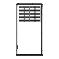
Covers installation procedures for the upflow configuration, including return air.

DOWNFLOW INSTALLATION

Details downflow installation requirements, including accessory use and floor preparation.

HORIZONTAL INSTALLATION

Instructions for installing the furnace in a horizontal orientation.

Roll-Out Protection

Provides protection against flame roll-out, especially in downflow positions.

Bottom Return Air Inlet

Procedure for removing the bottom closure panel for bottom return air.

Side Return Air Inlet

Notes regarding the bottom closure panel for side return air.

LOCATION RELATIVE TO COOLING EQUIPMENT

Guidelines for installing the furnace in relation to a cooling coil to prevent condensation.

Filter Arrangement

Information on the need for a field-supplied external filter rack.

AIR DUCTS

GENERAL REQUIREMENTS

Duct system design and sizing according to accepted national standards.

Ductwork Acoustical Treatment

Requirements for internal acoustical lining or fibrous ductwork.

SUPPLY AIRCONNECTIONS

Guidelines for connecting supply air ducts to the furnace outlet.

RETURN AIRCONNECTIONS

Instructions for connecting return air ducts to the furnace.

GAS PIPING

ELECTRICAL CONNECTIONS

J-BOX RELOCATION

ACCESSORIES

Electronic Air Cleaner (EAC)

Instructions for connecting an accessory Electronic Air Cleaner.

Humidifier (HUM)

Instructions for connecting an accessory Humidifier.

VENTING

GENERAL VENTING REQUIREMENTS

Follow all safety codes for proper vent sizing and installation requirements.

Chimney Inspection Chart

Guide for inspecting masonry chimneys for suitability with the furnace.

Masonry Chimney Requirement

Requirements for using masonry chimneys with a factory accessory Chimney Adapter Kit.

Appliance Application Requirements

How appliance operation impacts the performance of the venting system.

Additional Venting Requirements

Specific requirements for vent connectors and installation.

Sidewall Venting

Information on sidewall venting and approved mechanical venters.

START-UP, ADJUSTMENT, AND SAFETY CHECK

GENERAL

Pre-start checks including wiring, grounding, and gas pressure.

START-UP PROCEDURES

Step-by-step instructions for initiating furnace operation and safety checks.

ADJUSTMENTS

Furnace Overheating Hazard

Caution regarding furnace overheating and checking temperature rise.

Set Blower Off Delay

Instructions for setting the blower off delay based on desired heating mode.

Check Safety Controls

Check Main Limit Switch

Procedure to verify the proper operation of the main limit switch.

Check draft safeguard switch

Testing the draft safeguard switch for proper shutdown during blocked vent conditions.

Check Pressure Switch(es)

Procedure to verify the operation of the pressure switch for the draft inducer.

SERVICE AND MAINTENANCE PROCEDURES

GENERAL

General information on furnace installation orientation and electrical controls.

Electrical Controls and Wiring

Details on furnace wiring, polarity, grounding, and control system.

CARE AND MAINTENANCE

Cleaning and;or Replacing Air Filter

Procedures for cleaning or replacing the air filter and related instructions.

Blower Motor and Wheel

Instructions for cleaning the blower motor and wheel to ensure performance.

Cleaning Heat Exchanger

SEQUENCE OF OPERATION

Two-Stage Heating (Adaptive Mode) with Single-Stage Thermostat

Explains heating operation with a single-stage thermostat using adaptive control.

Inducer Prepurge Period

Details the prepurge sequence involving the inducer motor and pressure switches.

Two-Stage Thermostat and Two-Stage Heating

Describes heating operation with a two-stage thermostat and furnace control logic.

Cooling mode

Explains cooling operation with single-speed and two-speed thermostats.

Thermidistat Mode

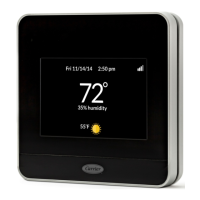
Details operation with a Thermidistat, including dehumidification and cooling.

Continuous Blower Mode

Describes the furnace operation with the blower running continuously.

Continuous Blower Speed Selection from Thermostat

How to adjust continuous blower airflow using the thermostat.

Heat pump

Explains furnace operation when paired with a heat pump system.

Component test

Procedure for initiating a component test to diagnose system problems.

Wiring Diagram

Troubleshooting

WIRING DIAGRAM

TROUBLESHOOTING GUIDE

PARTS REPLACEMENT INFORMATION GUIDE

CASING GROUP

List of replacement parts for the furnace casing.

ELECTRICAL GROUP

List of replacement parts for electrical components.

BLOWER GROUP

List of replacement parts for the blower assembly.

GAS CONTROL GROUP

List of replacement parts for gas control components.

HEAT EXCHANGER GROUP

List of replacement parts for the heat exchanger.

INDUCER GROUP

List of replacement parts for the inducer assembly.
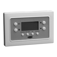
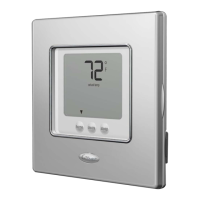
Related product manuals