PG80VTLA: Installation, Start-up, Operating and Service and Maintenance Instructions
Manufacturer reserves the right to change, at any time, specifications and designs without notice and without obligations.
8
2. For fan-assisted appliances such as this furnace:
A04003
• Iother = combined input of all other than fan-assisted appliances in
Btuh/hr
• Ifan = combined input of all fan-assisted appliances in Btuh/hr
• ACH = air changes per hour (ACH shall not exceed 0.60.)
Then the following requirements apply to both the Standard Method and
to the Known Air Infiltration Rate Method:
1. Adjoining rooms can be considered part of a space if:
a. There are no closeable doors between rooms.
b. Combining spaces on same floor level. Each opening shall have
free area of at least 1 in.
2
/1,000 Btuh (2,000 mm
2
/kW) of the
total input rating of all gas appliances in the space, but not less
than 100 in.
2
(0.06 m
2
). One opening shall commence within 12
in. (300 mm) of the ceiling and the second opening shall
commence within 12 in. (300 mm) of the floor. The minimum
dimension of air openings shall be at least 3 in. (80 mm). (See
Fig. 8).
c. Combining space on different floor levels. The volumes of
spaces on different floor levels shall be considered as
communicating spaces if connected by one or more permanent
openings in doors or floors having free area of at least 2
in.
2
/1,000 Btuh (4,400 mm
2
/kW) of total input rating of all gas
appliances.
2. An attic or crawlspace may be considered a space that freely
communicates with the outdoors provided there are adequate
permanent ventilation openings directly to outdoors having free
area of at least 1-in.2/4,000 Btuh of total input rating for all gas
appliances in the space.
c.
NP = Not Permitted
Note: Not all models have these sizes.
* Minimum opening size is 100 sq in. (64516 sq. mm) with
minimum dimensions of 3 in. (76 mm)
† Minimum of 3 in. (76 mm) when type-B1 vent is used.
a03175
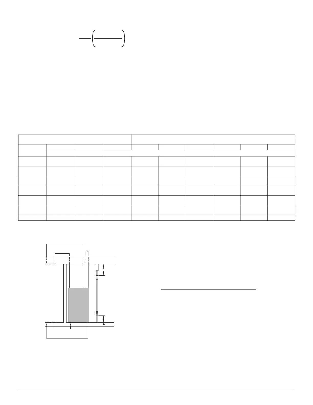
Fig. 8 – Air for Combustion, Ventilation,
and Dilution from Indoors
3. In spaces that use the Indoor Combustion Air Method, infiltration
should be adequate to provide air for combustion, permanent
ventilation and dilution of flue gases. However, in buildings with
unusually tight construction, additional air MUST be provided
using the methods described in the Outdoor Combustion Air
Method section.
4. Unusually tight construction is defined as Construction with:
a. Walls and ceilings exposed to the outdoors have a continuous,
sealed vapor barrier. Openings are gasketed or sealed and
b. Doors and openable windows are weatherstripped and
c. Other openings are caulked or sealed. These include joints
around window and door frames, between sole plates and floors,
between wall-ceiling joints, between wall panels, at penetrations
for plumbing, electrical and gas lines, etc.
Combination of Indoor and Outdoor Air
1. Indoor openings shall comply with the Indoor Combustion Air
Method below and,
2. Outdoor openings shall be located as required in the Outdoor
Combustion Air Method mentioned previously and,
3. Outdoor openings shall be sized as follows:
a. Calculate the Ratio of all Indoor Space volume divided by
required volume for Indoor Combustion Air Method below.
b. Outdoor opening size reduction Factor is 1 minus the Ratio in a.
above.
c. Minimum size of Outdoor openings shall be the size required in
Outdoor Combustion Air Method above multiplied by
reduction Factor in b. above. The minimum dimension of air
openings shall be not less than 3 in. (80 mm).
Volume
Fan
=
15ft
3
ACH
I
fan
1000 Btu/hr
Table 2 – Minimum Space Volumes for 100% Combustion, Ventilation, and Dilution from Indoors
OTHER THAN FAN-ASSISTED TOTAL
(1,000’S BTUH GAS INPUT RATE)
FAN-ASSISTED TOTAL
(1,000’S BTUH GAS INPUT RATE)
ACH
30 40 50 44 66 88 110 132 154
Space Volume Ft
3
(M
3
)
0.60
1,050
(29.7)
1,400
(39.6)
1,750
(49.5)
1,100
(31.1)
1,650
(46.7)
2,200
(62.2)
2,750
(77.8)
3,300
(93.4)
3,850
(109.0)
0.50
1,260
(35.6)
1,680
(47.5)
2,100
(59.4)
1,320
(37.3)
1,980
(56.0)
2,640
(74.7)
3,300
(93.4)
3,960
(112.1)
4,620
(130.8)
0.40
1,575
(44.5)
2,100
(59.4)
2,625
(74.3)
1,650
(46.7)
2,475
(70.0)
3,300
(93.4)
4,125
116.8)
4,950
(140.1)
5,775
(163.5)
0.30
2,100
(59.4)
2,800
(79.2)
3,500
(99.1)
2,200
(62.2)
3,300
(93.4)
4,400
(124.5)
5,500
(155.7)
6,600
(186.8)
7,700
(218.0)
0.20
3,150
(89.1)
4,200
(118.9)
5,250
(148.6)
3,300
(93.4)
4,950
(140.1)
6,600
(186.8)
8,250
(233.6)
9,900
(280.3)
11,550
(327.0)
0.10
6,300
(178.3)
8,400
(237.8)
10,500 (297.3)
6,600
(186.8)
9,900
(280.3)
13,200
(373.7)
16,500
(467.2)
19,800
(560.6)
23,100
(654.1)
0.00 NP NP NP NP NP NP NP NP NP
CIRCULATING AIR
DUCTS
6" MIN
(FRONT)
Ü
CIRCULATING AIR DUCTS
VENT THROUGH ROOF
1 SQ IN.
PER 1000
BTUH* IN DOOR
OR WALL
12" MAX
1 SQ IN.
PER 1000
BTUH* IN DOOR
OR WALL
12" MAX
UNCONFINED
SPACE
INTERIOR
HEATED
SPACE
CLEARANCE IN FRONT OF COMBUSTION AIR
O PE NI N GS S H AL L BE AT LEAST 3 IN.
(305mm)
(152mm)
(305mm)

 Loading...