PG80VTLA: Installation, Start-up, Operating and Service and Maintenance Instructions
Manufacturer reserves the right to change, at any time, specifications and designs without notice and without obligations.
12
Refer to the instructions supplied with the external filter rack for
assembly and installation options.
AIR DUCTS
GENERAL REQUIREMENTS
The duct system should be designed and sized according to accepted
national standards such as those published by: Air Conditioning
Contractors Association (ACCA), Sheet Metal and Air Conditioning
Contractors National Association (SMACNA) or American Society of
Heating, Refrigerating and Air Conditioning Engineers (ASHRAE) or
consult The Air Systems Design Guidelines reference tables available
from your local distributor. The duct system should be sized to handle
the required system design CFM at the design external static pressure.
The furnace airflow rates are provided in Table 4-Air Delivery-CFM
(With Filter). When a furnace is installed so that the supply ducts carry
air circulated by the furnace to areas outside the space containing the
furnace, the return air shall also be handled by duct(s) sealed to the
furnace casing and terminating outside the space containing the furnace.
Secure ductwork with proper fasteners for type of ductwork used. Seal
supply- and return-duct connections to furnace with code approved tape
or duct sealer.
NOTE: Flexible connections should be used between ductwork and
furnace to prevent transmission of vibration.
Ductwork passing through unconditioned space should be insulated to
enhance system performance. When air conditioning is used, a vapor
barrier is recommended.
Maintain a 1-in. (25 mm) clearance from combustible materials to
supply air ductwork for a distance of 36-in. (914 mm) horizontally from
the furnace. See NFPA 90B or local code for further requirements.
Ductwork Acoustical Treatment
NOTE: Metal duct systems that do not have a 90 degree elbow and 10
ft. (3 M) of main duct to the first branch take-off may require internal
acoustical lining. As an alternative, fibrous ductwork may be used if
constructed and installed in accordance with the latest edition of
SMACNA construction standard on fibrous glass ducts. Both acoustical
lining and fibrous ductwork shall comply with NFPA 90B as tested by
UL Standard 181 for Class 1 Rigid air ducts.
SUPPLY AIR CONNECTIONS
For a furnace not equipped with a cooling coil, the outlet duct shall be
provided with a removable access panel. This opening shall be
accessible when the furnace is installed and shall be of such a size that
the heat exchanger can be viewed for possible openings using light
assistance or a probe can be inserted for sampling the air stream. The
cover attachment shall prevent leaks.
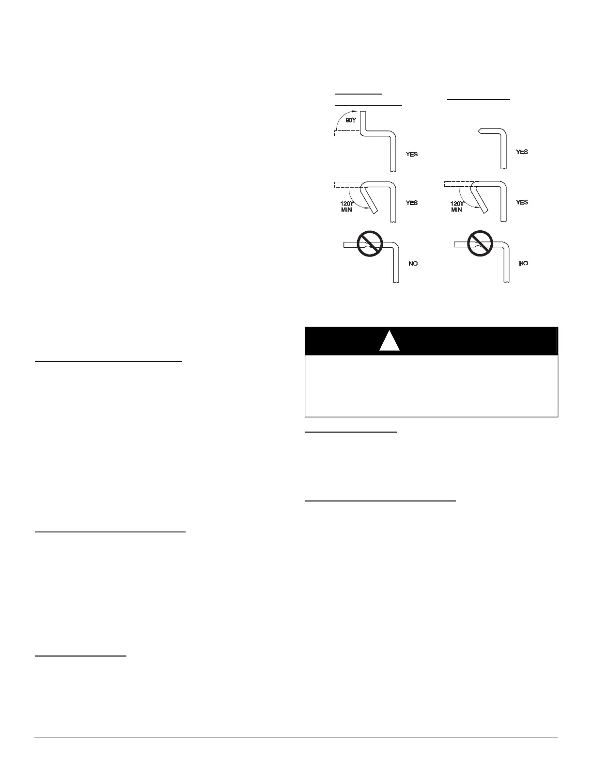
Upflow and Horizontal Furnaces
Connect supply-air duct to flanges on furnace supply-air outlet. Bend
flange upward to 90° with wide duct pliers. (See Fig. 17). The supply-air
duct must be connected to ONLY the furnace supply-outlet-air duct
flanges or air conditioning coil casing (when used). DO NOT cut main
furnace casing side to attach supply air duct, humidifier, or other
accessories. All accessories MUST be connected to duct external to
furnace main casing.
NOTE: For horizontal applications, the top most flange may be bent
past 90° to allow the evaporator coil to hang on the flange temporarily
while the remaining attachment and sealing of the coil are performed.
Downflow Furnaces
Connect supply-air duct to supply-air outlet on furnace. Bend flange
inward past 90° with wide duct pliers (See Fig. 17). The supply-air duct
must be connected to ONLY the furnace supply outlet or air conditioning
coil casing (when used). When installed on combustible material,
supply-air duct must be connected to ONLY the factory-approved
accessory subbase, or a factory-approved air conditioning coil casing.
DO NOT cut main furnace casing to attach supply side air duct,
humidifier, or other accessories. All accessories MUST be connected to
duct external to furnace casing.
A190346
Fig. 17 – Duct Flanges
RETURN AIR CONNECTIONS
Downflow Furnaces
The return-air duct must be connected to return-air opening bottom inlet.
(See Fig. 1). DO NOT cut into casing sides (left or right). Side opening
is permitted for only upflow and certain horizontal furnaces. Bypass
humidifier connections should be made at ductwork or coil casing sides
exterior to furnace. (See Fig. 18).
Upflow and Horizontal Furnaces
The return-air duct must be connected to bottom, sides (left or right), or a
combination of bottom and side(s) of main furnace casing. (See Fig. 1).
Bypass humidifier may be attached into unused return air side of the
furnace casing. (See Fig. 19 and Fig. 20). Not all upflow and horizontal
furnace models are approved for side return air connections. (See Fig. 19
and Fig. 20).
WARNING
!
FIRE HAZARD
A failure to follow this warning could cause personal injury, death
and/or property damage.
Never connect return-air ducts to the back of the furnace. Follow
instructions below.
UPFLOW/
HORIZONTAL
DOWNFLOW

 Loading...