PG80VTLA: Installation, Start-up, Operating and Service and Maintenance Instructions
Manufacturer reserves the right to change, at any time, specifications and designs without notice and without obligations.
10
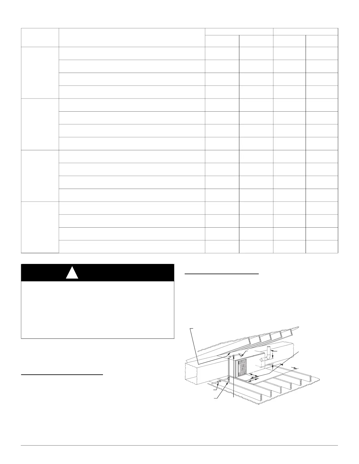
HORIZONTAL INSTALLATION
The furnace can be installed horizontally in an attic or crawlspace on
either the left-hand (LH) or right-hand (RH) side. The furnace can be
hung from floor joists, rafters or trusses or installed on a
non-combustible platform, blocks, bricks or pad.
Suspended Furnace Support
The furnace may be supported under each end with threaded rod, angle
iron or metal plumber’s strap as shown. (See Fig. 14 and Fig. 15). Secure
angle iron to bottom of furnace as shown. Heavy-gauge sheet metal
straps (plumber’s straps) may be used to suspend the furnace from each
bottom corner. To prevent screws from pulling out, use 2 #8 x 3/4 in.
screws into the side and 2 #8 x in. screws in the bottom of the furnace
casing for each strap. (See Fig. 14 and Fig. 15).
If the screws are attached to ONLY the furnace sides and not the bottom,
the straps must be vertical against the furnace sides and not pull away
from the furnace sides, so that the strap attachment screws are not in
tension (are loaded in shear) for reliable support.
Platform Furnace Support
Construct working platform at location where all required furnace
clearances are met. (See Fig. 2 and Fig. 13). For furnaces with 1-in. (25
mm) clearance requirement on side, set furnace on non-combustible
blocks, bricks or angle iron. For crawlspace installations, if the furnace
is not suspended from the floor joists, the ground underneath furnace
must be level and the furnace set on blocks or bricks.
A10164
Fig. 13 – Typical Attic Installation
Table 3 – Opening Dimensions - In. (mm)
FURNACE
CASING
WIDTH
APPLICATION
PLENUM OPENING FLOOR OPENING
A B C D
14–3/16
(360)
Upflow Applications on Combustible or Noncombustible Flooring (subbase
not required)
12-11/16
(322)
21-5/8
(549)
13-5/16
(338)
22-1/4
(565)
Downflow Applications on Noncombustible Flooring
(subbase not required)
12-9/16
(319)
19
(483)
13-3/16
(335)
19-5/8
(498)
Downflow Applications on Combustible Flooring
(subbase required)
11-13/16
(284)
19
(483)
13-7/16
(341)
20-5/8
(600)
Downflow Applications on Combustible Flooring with Cased Coil (subbase
not required)
12-5/16
(319)
19
(483)
13-5/16
(338)
20
(508)
17–1/2
(445)
Upflow Applications on Combustible or Noncombustible Flooring (subbase
not required)
16
(406)
21-5/8
(549)
16-5/8
(422)
22-1/4
(565)
Downflow Applications on Noncombustible Flooring
(subbase not required)
15-7/8
(403)
19
(483)
16-1/2
(419)
19-5/8
(498)
Downflow Applications on Combustible Flooring
(subbase required)
15-1/8
(384)
19
(483)
16-3/4
(425)
20-5/8
(600)
Downflow Applications on Combustible Flooring with Cased Coil (subbase
not required)
15-1/2
(394)
19
(483)
16-1/2
(419)
20
(508)
21
(533)
Upflow Applications on Combustible or Noncombustible Flooring (subbase
not required)
19-1/2
(495)
21-5/8
(549)
20-1/8
(511)
22-1/4
(565)
Downflow Applications on Noncombustible Flooring
(subbase not required)
19-3/8
(492)
19
(483)
20
(508)
19-5/8
(498)
Downflow Applications on Combustible Flooring
(subbase required)
18-5/8
(473)
19
(483)
20-1/4
(514)
20-5/8
(600)
Downflow Applications on Combustible Flooring with Cased Coil (subbase
not required)
19
(483)
19
(483)
20
(508)
20
(508)
24-1/2
(622)
Upflow Applications on Combustible or Noncombustible Flooring (subbase
not required)
23
(584)
21-1/8
(537)
23-5/8
(600)
22-1/4
(565)
Downflow Applications on Noncombustible Flooring
(subbase not required)
22-7/8
(581)
19
(483)
23-1/2
(597)
19-5/8
(498)
Downflow Applications on Combustible Flooring
(subbase required)
22-1/8
(562)
19
(483)
23-3/4
(603)
20-5/8
(600)
Downflow Applications on Combustible Flooring with Cased Coil (subbase
not required)
22-1/2
(572)
19
(483)
23-1/2
(597)
20
(508)
WARNING
!
FIRE, EXPLOSION, AND CARBON MONOXIDE
POISONING HAZARD
Failure to follow this warning could result in personal injury, death, or
property damage.
Do not install the furnace on its back or hang furnace with control
compartment facing downward. Safety control operation will be
adversely affected. Never connect return-air ducts to the back of the
furnace.
30-IN. (762mm)
MIN WORK AREA
6″ MIN*
TYPE-B
VENT
17
3
/4
″
22
″
SHEET
METAL
SEDIMENT
TRAP
EQUIPMENT MANUAL
SHUT-OFF GAS VALVE
LINE CONTACT ONLY PERMISSIBLE BETWEEN
LINES FORMED BY INTERSECTIONS OF
THE TOP AND TWO SIDES OF THE FURNACE
JACKET AND BUILDING JOISTS,
STUDS, OR FRAMING.
GAS
ENTRY
17
3
/4
″
(451mm)
OVERALL
4
3
/4
″
(121mm)
UNDER DOOR
1″
(25mm)
UNDER FURNACE
EXTEND OUT 12″
(305mm)
FROM FACE OF DOOR
* WHEN USED WITH
SINGLE WALL VENT
CONNECTIONS
UNION
(152mm)
(451mm)
(559mm)

 Loading...