PG80VTLA: Installation, Start-up, Operating and Service and Maintenance Instructions
Manufacturer reserves the right to change, at any time, specifications and designs without notice and without obligations.
9
INSTALLATION
UPFLOW INSTALLATION
Bottom Return Air Inlet
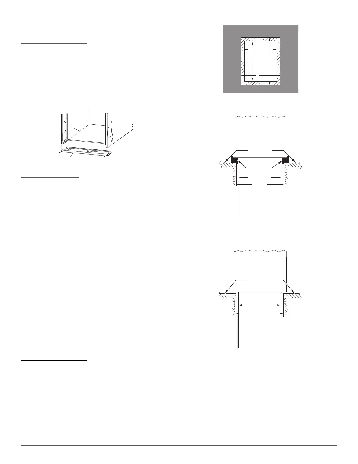
These furnaces are shipped with bottom closure panel installed in bottom
return-air opening. Remove and discard this panel when bottom return
air is used. To remove bottom closure panel, perform the following:
1. Tilt or raise furnace and remove 2 screws holding bottom filler
panel. (See Fig. 9).
2. Rotate bottom filler panel downward to release holding tabs.
3. Remove bottom closure panel.
4. Reinstall bottom filler panel and screws.
A10273
Fig. 9 – Removing Bottom Closure Panel
Side Return Air Inlet
These furnaces are shipped with bottom closure panel installed in bottom
return-air opening. This panel MUST be in place when only side return
air is used.
NOTE: Side return-air openings can be used in UPFLOW and most
HORIZONTAL configurations. Do not use side return-air openings in
DOWNFLOW configuration.
DOWNFLOW INSTALLATION
NOTE: For downflow applications, this furnace is approved for use on
combustible flooring when any one of the following 3 accessories are
used:
• Special Base, KGASB
• Cased Coil Assembly Part No. CNPV, CNRV, CAP, or CAR
• Coil Box Part No. KCAKC
1. Determine application being installed from Table 3.
2. Construct hole in floor. (See Table 3 and Fig. 10).
3. Construct plenum to dimensions specified. (See Table 3 and
Fig. 10).
4. If downflow subbase, KGASB is used, install as shown. (See
Fig. 11). If Coil Assembly Part No. CPVP, CAPMP or CNPVP Coil
Box Part No. KCAKC is used, install as shown. (See Fig. 12).
NOTE: It is recommended that the perforated supply-air duct flanges be
completely folded over or removed from furnace when installing the
furnace on a factory-supplied cased coil or coil box. To remove the
supply-air duct flange, use wide duct pliers or hand seamers to bend
flange back and forth until it breaks off. Be careful of sharp edges.
(Refer to Duct Flanges (Fig. 17) in the “Air Ducts” section.)
Bottom Return Air Inlet
These furnaces are shipped with bottom closure panel installed in bottom
return-air opening. Remove and discard this panel when bottom return
air is used. To remove bottom closure panel, perform the following:
1. Tilt or raise furnace and remove 2 screws holding bottom filler
panel. (See Fig. 9).
2. Rotate bottom filler panel downward to release holding tabs.
3. Remove bottom closure panel.
4. Reinstall bottom filler panel and screws.
A96283
Fig. 10 – Floor and Plenum Opening Dimensions
A96285
Fig. 11 – Furnace, Plenum, and Subbase
Installed on a Combustible Floor
A08556
Fig. 12 – Furnace, Plenum, and Coil Assembly or
Coil Box Installed on a Combustible Floor
Bottom
Closure Panel
Bottom Filler Panel
PLENUM
OPENING
C
A
B
D
FLOOR
OPENING
DOWNFLOW
SUBBASE
SHEET METAL
PLENUM
FLOOR
OPENING
FURNACE
(OR COIL CASING
WHEN USED)
COMBUSTIBLE
FLOORING
APPROVED
COIL ASSEMBLY
OR
COIL BOX
FURNACE
SHEET METAL
PLENUM
FLOOR
OPENING
COMBUSTIBLE
FLOORING

 Loading...