PG80VTLA: Installation, Start-up, Operating and Service and Maintenance Instructions
Manufacturer reserves the right to change, at any time, specifications and designs without notice and without obligations.
31
A02068
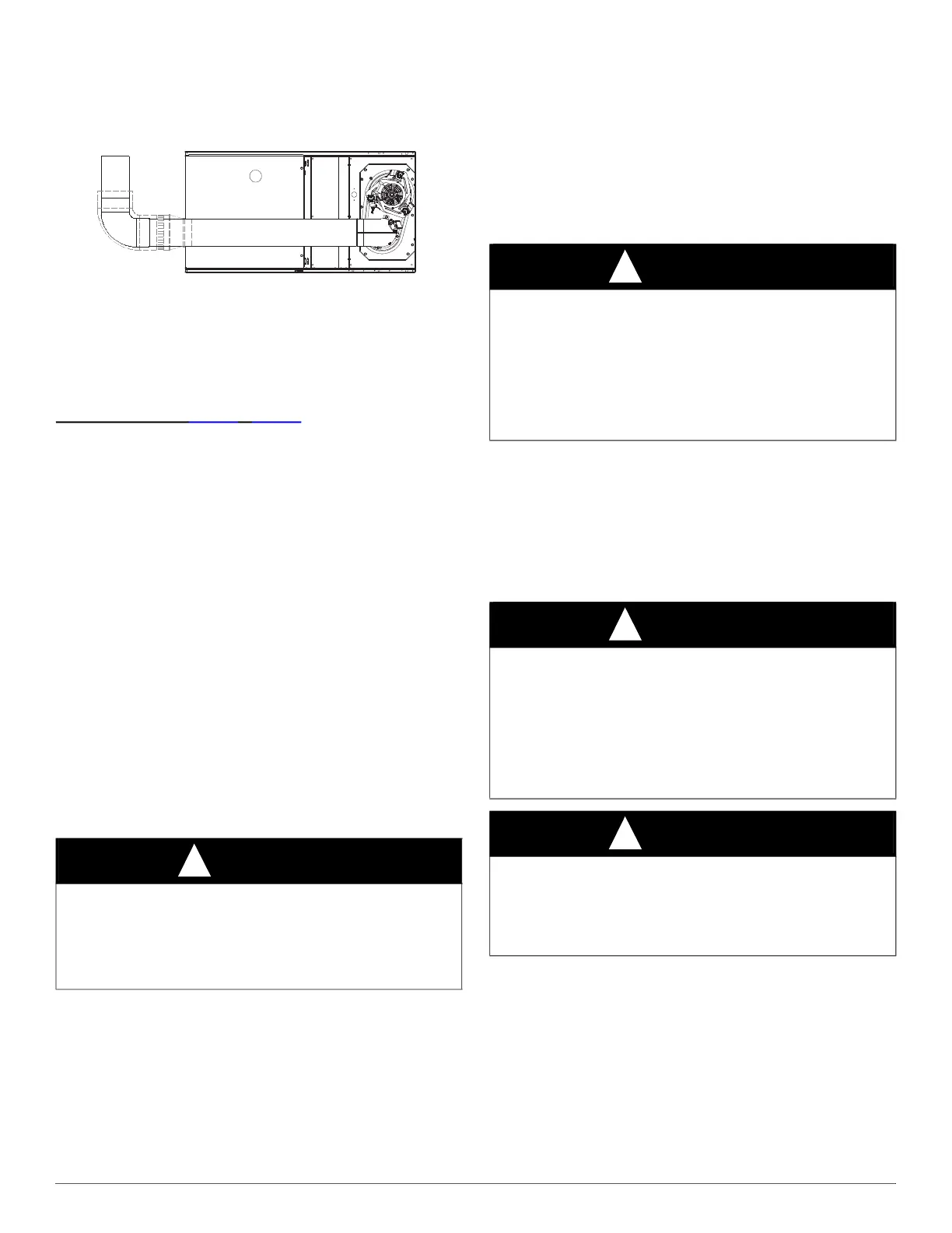
Fig. 50 – Horizontal Right Application-Vent Elbow Left
Venting Notes for Fig. 38 - Fig. 50
1. For common vent, vent connector sizing and vent material: United
States--use the NFGC.
2. Immediately increase to 5-in. (102 mm) or 6-in. (152 mm) vent
connector outside furnace casing when 5-in. (127 mm) vent
connector is required, refer to Note 1 above.
3. Side outlet vent for upflow and downflow installations must use
Type B vent immediately after exiting the furnace, except when
factory-approved Downflow Vent Guard Kit is used in the
downflow position. See Product Data Sheet for accessory listing.
4. Type-B vent where required, refer to Note 1 above.
5. A 4-in.(102 mm) single-wall (26 ga. min.) vent must be used inside
furnace casing and when the factory-approved Downflow Vent
Guard Kit is used external to the furnace. See Product Data Sheet
for accessory listing.
6. Accessory Downflow Vent Guard Kit required in downflow
installations with lower vent configuration. See Product Data Sheet
for accessory listing.
7. Chimney Adapter Kit may be required for exterior masonry
chimney applications. Refer to Chimney Adapter Kit for sizing and
complete application details. See Product Data Sheet for accessory
listing.
8. Secure vent connector to furnace elbow with (2) corrosion-resistant
sheet metal screws, spaced approximately 180_ apart.
9. Secure all other single wall vent connector joints with (3) corrosion
resistant screws spaced approximately 120_ apart. Secure Type-B
vent connectors per vent connector manufacturer’s
recommendations.
START-UP, ADJUSTMENT, AND SAFETY
CHECK
GENERAL
1. Maintain 115-v wiring and ground. Improper polarity will result in
rapid flashing LED and no furnace operation.
2. Make thermostat wire connections at the 24-v terminal block on the
furnace control. Failure to make proper connections will result in
improper operation. (See Fig. 24 - Fig. 36).
3. Gas supply pressure to the furnace must be greater than 4.5-In.
W.C. (0.16 psig ) but not exceed 14-In. W.C. (0.5 psig).
4. Check all manual-reset switches for continuity.
5. Replace blower compartment door. Door must be in place to
operate furnace.
6. Setup switch descriptions. The variable speed furnace control has
DIP switches to select thermostat staging, blower off delay timings,
air flow selection and other operational or service related functions.
(See Fig. 36, Fig. 54, and Fig. 59).
START-UP PROCEDURES
1. Purge gas lines after all connections have been made.
2. Check gas lines for leaks.
3. To Begin Component Self-Test:
a. Remove Blower Access Door.
b. Disconnect the thermostat R lead from furnace control board.
c. Manually close blower door switch.
d. Turn Setup DIP switch SW1-6 ON. (See Fig. 36, Fig. 54, and
Fig. 59).
NOTE: The furnace control allows all components, except the gas
valve, to be run for short period of time. This feature helps diagnose a
system problem in case of a component failure. Component test feature
CAUTION
!
CUT HAZARD
Failure to follow this caution may result in personal injury.
Sheet metal parts may have sharp edges or burrs. Use care and wear
appropriate protective clothing, safety glasses and gloves when
handling parts, and servicing furnaces.
WARNING
!
FIRE HAZARD
Failure to follow this warning could result in personal injury, death or
property damage.
This furnace is equipped with manual reset limit switches in the gas
control area. The switches open and shut off power to the gas valve, if a
flame rollout or overheating condition occurs in the gas control area.
DO NOT bypass the switches. Correct problem before resetting the
switches.
WARNING
!
FIRE OR EXPLOSION HAZARD
Failure to follow this warning could result in personal injury, death,
and/or property damage.
Never purge a gas line into a combustion chamber. Never test for gas
leaks with an open flame. Use a commercially available soap solution
made specifically for the detection of leaks to check all connections. A
fire or explosion may result causing property damage, personal injury
or loss of life.
WARNING
!
ELECTRICAL SHOCK HAZARD
Failure to follow this warning could result in personal injury, or death.
Blower access door switch opens 115-v power to control. No
component operation can occur unless switch is closed. Caution must
be taken when manually closing this switch for service purposes.

 Loading...