PG80VTLA: Installation, Start-up, Operating and Service and Maintenance Instructions
Manufacturer reserves the right to change, at any time, specifications and designs without notice and without obligations.
34
l. Proceed to Step 6, “Set Blower Off Delay” before installing
blower access door.
7. Set Blower Off Delay. (See Table 10.)
a. Remove blower access door if installed.
b. Turn Dip switch SW-7 or SW-8 ON or OFF for desired blower
off delay. (See Fig. 36, Fig. 54 and Fig. 59).
8. Set thermostat heat anticipator.
a. Mechanical thermostat. Set thermostat heat anticipator to match
the amp. draw of the electrical components in the R-W/W1
circuit. Accurate amp. draw readings can be obtained at the wires
normally connected to thermostat subbase terminals, R and W.
The thermostat anticipator should NOT be in the circuit while
measuring current.
(1.) Set SW1-2 switch on furnace control board to ON.
(2.) Remove thermostat from subbase or from wall.
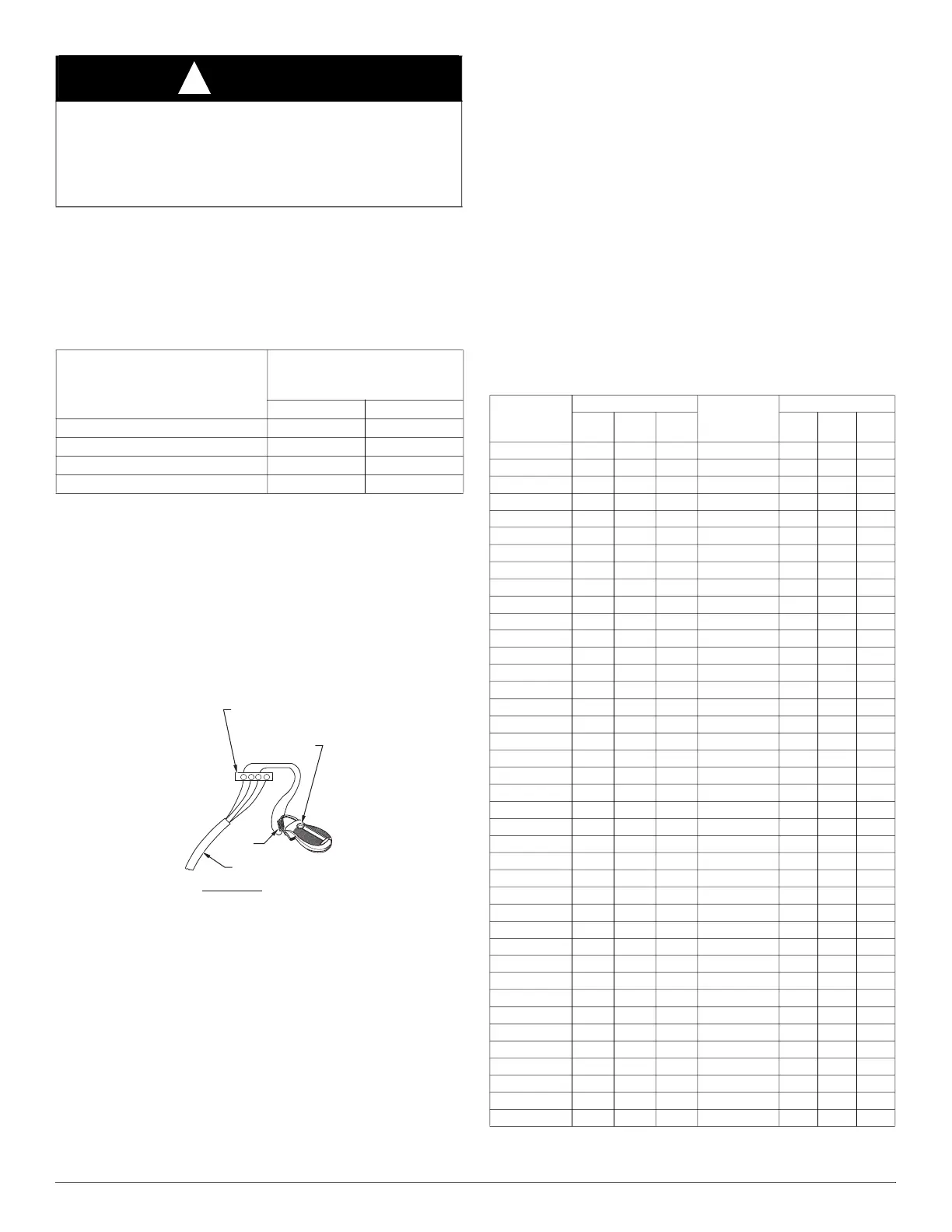
(3.) Connect an amp. meter across the R and W subbase
terminals or R and W wires at wall. (See Fig. 52.
A96316
Fig. 52 – Amp. Draw Check with Ammeter
(4.) Record amp. draw across terminals when furnace is in low
heat and after blower starts.
(5.) Set heat anticipator on thermostat per thermostat
instructions and install on subbase or wall.
(6.) Turn SW1-2 switch OFF.
(7.) Install blower access door.
b. Electronic thermostat: Set cycle rate for 3 cycles per hr.
9. Set Airflow for Air Conditioning -Single Stage and High Stage
Cooling.
The ECM blower can be adjusted for a range of airflow for Low
Speed or High Speed cooling. See Table 4-Air Delivery - CFM
(With Filter).
The cooling airflow is adjusted by turning Setup switches SW2-6,
SW2-7 and SW2-8 either ON or OFF. Select the required airflow.
(See Fig. 55).
NOTE: 5.5 ton airflow will truncate at 2200 cfm on applicable models.
For a complete explanation of cooling airflow, refer to the section titled
“Sequence of Operation.”
10. The Continuous Fan airflow selection via Setup switches SW2-3,
SW2-4, SW2-5 is also the switch setting for low-speed cooling
when the furnace is used with a two-speed cooling or heat pump
unit. Refer to the Adjustments section (also Fig. 54 and Fig. 55) for
setup switch configurations. This setup feature allows continuous
fan airflow or low-cooling airflow to be adjusted.
The continuous fan speed can be further adjusted at the thermostat
using the Continuous Blower Speed Selection from Thermostat
function. Changing the continuous fan speed at the thermostat
DOES NOT change the low speed cooling airflow selected at the
control board. See the section titled Continuous Blower Speed
Selection from Thermostat in the Sequence of Operation section of
this document.
CAUTION
!
FURNACE OVERHEATING HAZARD
Failure to follow this caution may result in reduced furnace life.
Recheck temperature rise. It must be within limits specified on the
rating plate. Recommended operation is at the mid-point of rise range
or slightly above.
Table 10 – Blower Off Delay Setup Switch
DESIRED HEATING MODE
BLOWER OFF DELAY (SEC.)
SETUP SWITCH
(SW-7 AND -8)
POSITION
SW1-7 SW1-8
90 OFF OFF
120 ON OFF
150 OFF ON
180 ON ON
R Y W G
10 TURNS
THERMOSTAT SUBBASE
TERMINALS WITH
THERMOSTAT REMOVED
(ANITICIPATOR, CLOCK, ETC.,
MUST BE OUT OF CIRCUIT.)
HOOK-AROUND
AMMETER
EXAMPLE:
5.0 AMPS ON AMMETER
10 TURNS AROUND JAWS
=
0.5 AMPS FOR THERMOSTAT
ANTICIPATOR SETTING
FROM UNIT 24-V
CONTROL TERMINALS
Table 11 – Gas Rate (CU ft./hr)
SECONDS G
FOR 1
REVOLUTION
SIZE OF TEST DIAL
SECONDS
FOR 1
REVOLUTION
SIZE OF TEST DIAL
1 Cu
Ft.
2 Cu
Ft.
5 Cu
Ft.
1 Cu
Ft.
2 Cu
Ft.
5 Cu
Ft.
10 360 720 1800 50 72 144 360
11 327 655 1636 51 71 141 355
12 300 600 1500 52 69 138 346
13 277 555 1385 53 68 136 340
14 257 514 1286 54 67 133 333
15 240 480 1200 55 65 131 327
16 225 450 1125 56 64 129 321
17 212 424 1059 57 63 126 316
18 200 400 1000 58 62 124 310
19 189 379 947 59 61 122 305
20 180 360 900 60 60 120 300
21 171 343 857 62 58 116 290
22 164 327 818 64 56 112 281
23 157 313 783 66 54 109 273
24 150 300 750 68 53 106 265
25 144 288 720 70 51 103 257
26 138 277 692 72 50 100 250
27 133 267 667 74 48 97 243
28 129 257 643 76 47 95 237
29 124 248 621 78 46 92 231
30 120 240 600 80 45 90 225
31 116 232 581 82 44 88 220
32 113 225 563 84 43 86 214
33 109 218 545 86 42 84 209
34 106 212 529 88 41 82 205
35 103 206 514 90 40 80 200
36 100 200 500 92 39 78 196
37 97 195 486 94 38 76 192
38 95 189 474 96 38 75 188
39 92 185 462 98 37 74 184
40 90 180 450 100 36 72 180
41 88 176 439 102 35 71 178
42 86 172 429 104 35 69 173
43 84 167 419 106 34 68 170
44 82 164 409 108 33 67 167
45 80 160 400 110 33 65 164
46 78 157 391 112 32 64 161
47 76 153 383 116 31 62 155
48 75 150 375 120 30 60 150
49 73 147 367

 Loading...