Do you have a question about the Carrier KJR-120G1/TFBG-E and is the answer not in the manual?
Defines warning and caution symbols and their implications for safety.
Lists critical safety instructions like professional installation and handling flammable gases.
Details notes on preventing electric shock, proper wiring, and cable handling.
Advises on choosing a suitable location, avoiding oil, vapor, or gas.
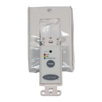
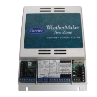
Lists required parts and assemblies for installation.
Provides crucial safety notes regarding wiring, voltage, and grounding.
Shows physical dimensions, structure, and basic wiring diagram.
Detailed wiring diagram for Model A.
Detailed wiring diagram for Model B.
Guides on removing the upper casing and fastening the back plate.
Details flush mounting and battery installation.
Demonstrates three ways to wire the controller to the indoor unit.
Instructions on sealing wires and reassembling the controller.
Lists input voltage, operating temperature, and humidity.
Details wiring type, size, and maximum cable length.
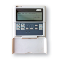
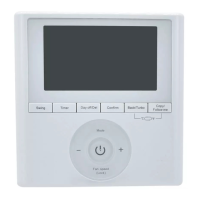
Highlights key features like LCD display, error code display, and wiring design.
Lists operational functions such as mode, fan speed, timer, and child lock.
Identifies and explains various icons and indicators displayed on the controller's LCD.
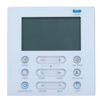
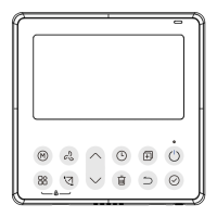
Labels and explains the function of each button on the wire controller.
Step-by-step guide to setting the day and current time on the controller.
Instructions on turning the unit on/off and selecting operating modes.
Details how to adjust the desired room temperature using the '+' and '-' buttons.
How to adjust fan speed and select room temperature sensor.
How to manage child lock, keypad tone, and temperature scale.
Explains Turbo/PTC and lift panel operations.
How to activate and control vertical and horizontal airflow swing.
Operation for controlling up-down airflow direction, including individual louver control.
Introduces Weekly, On, Off, and On/Off timers.
Step-by-step guide to configure single ON or OFF timer settings.
Guide to setting both ON and OFF times for a single operation cycle.
Initiates the process for setting up the weekly timer schedule.
Selects the day and configures ON time, mode, temp, fan speed.
Sets time, operation mode, and room temperature for weekly timer.
Sets fan speed and instructions for repeating settings.
How to start, cancel weekly timer and set DAY OFF.
How to copy timer settings from one day to another.
How to remove specific time scale entries from the weekly timer.
Lists common error codes (F0, F1) and their meanings.
Guidance on what to do if other error codes appear.
States compliance with CE certification requirements for EMC and EMI.
| Display | LCD |
|---|---|
| Communication | Wired |
| Wired | Yes |
| Control Method | Button |
| Operating Temperature | -10°C to 50°C |
| Type | Wired Remote Controller |
| Application | HVAC Systems |
| Humidity Range | 40% to 90% RH |