EasyManua.ls Logo

Carrier KVACN0101AC - User Manual

Carrier KVACN0101AC
2 pages
Print Icon
To Next Page IconTo Next Page
Loading...
Installation and User Guide
READ AND SAVE THESE INSTRUCTIONS
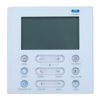
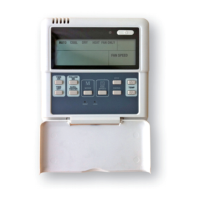
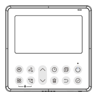
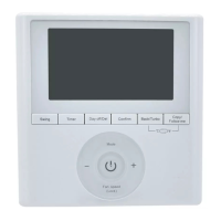
The illustrations in this document are generic; your control appearance may be slightly different from the ones shown.
INSTALLATION
1. Unplug the ventilation unit.
NOTE: If the control is to be installed in an electric box, go to step 5.
2. Cut a 27/8" x 1¾" hole in a wall, at a convenient location for the
control. Route a cable (type 22/4) for the control from the unit to
this hole.
A200529
3. Temporarily place the control over the hole and mark both
mounting screw hole positions.
4. Remove the control, drill both screw holes (3/16" Ø) in wall and
insert the wall anchors (included).
A200530
5. Strip the end of the cable to access the 4 wires (about 3"). Strip the
end of each wire (about 1/4"). Connect the wires to the terminals,
regardless of the wire color. Note which wire color has been chosen
for each terminal.
A200531
6. Mount the control to the wall.
A200532
KVACN0101(B,C)AC
Automatic Control
WARNING
!
ELECTRICAL SHOCK HAZARD
Failure to follow this warning could result in personal injury or death.
Electrical wiring must be done by qualified personnel in accordance
with all applicable codes and standards. Before connecting wires,
unplug the unit or switch power off at service panel and lock service
disconnecting means to prevent power from being switched on
accidentally. Always wear safety glasses and gloves while performing
these instructions.
CAUTION
!
PROPERTY DAMAGE HAZARD
Failure to comply with the following can cause damage.
If ducts have to go through an unconditioned space (e.g.: attic), always
use insulated ducts to prevent condensation formation inside and
outside ducts, which could cause material damage and/or mold growth.
Moreover, if fresh air to building duct and/or stale air from building
duct goes/go through an unconditioned space, the unit must be set to
operate continuously in cold conditions (below 10°C/50°F).
Continuous air movement inside ducts will prevent condensation
formation. The unit can be stopped temporarily for maintenance and/or
repair purposes in such conditions. (Refer to the main unit Installer
Manual for more details.)
Question and Answer IconNeed help?

Do you have a question about the Carrier KVACN0101AC and is the answer not in the manual?

Summary

Important Safety Instructions

Electrical Shock Hazard Warning

Warning regarding electrical wiring by unqualified personnel and the need to de-energize the unit before work.

Property Damage Hazard Caution

Caution on preventing condensation in unconditioned spaces and setting unit for cold conditions to prevent damage.

Installation Procedure

Wall Preparation and Control Mounting

Steps for cutting a wall hole, marking screw positions, drilling, inserting anchors, and mounting the control unit.

Wiring and Connection

Instructions on stripping wires, connecting them to terminals, and performing electrical connections to the unit.

Control Operation

Mode Selection and Indicators

Explanation of indicator lights and operational modes like RECIRC, INT, MIN/MED/MAX, TURBO, and AUTO.

Automatic Temperature Control

Details on how the AUTO mode operates based on outdoor temperature ranges and ventilation speeds.

Maintenance and Troubleshooting Alerts

Information on the maintenance indicator, filter cleaning/replacement, and troubleshooting communication errors.

Carrier KVACN0101AC Specifications

General IconGeneral
BrandCarrier
ModelKVACN0101AC
CategoryController
LanguageEnglish

Related product manuals