Manufacturer reserves the right to discontinue, or change at any time, specifications or designs without notice and without incurring obligations.
Catalog No. 20-40VM9005-01 Printed in U.S.A. Form 40VM-4SI R1 Pg 14 08-20
Replaces: 40VM-4SI
© Carrier Corporation 2020
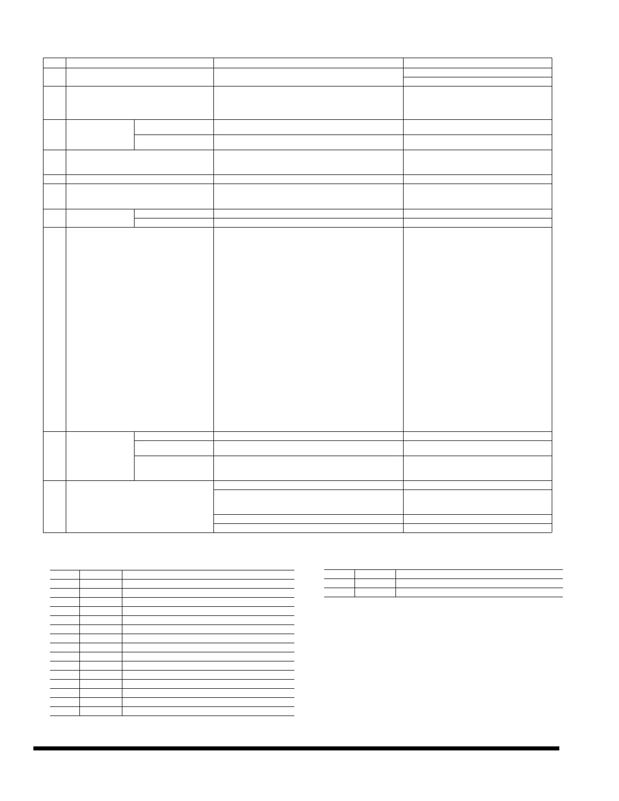
Table 7 —Parameter Details
No. SERVICE menu Description Set parameter
1 ROOM TEMP SENSOR LOCATION
Select whether to use the IDU room temperature sensor or the room
temperature sensor of the wired controller.
INDOOR UNIT
WIRD REMOTE CONTROL (default)
2 ROOM TEMP SENSOR OFFSET The temperature compensation value for wired controller T1
-5ºF, -4ºF, -3ºF, -2ºF, -1ºF, 0ºF (default), 1ºF, 2ºF, 3ºF,
4ºF, 5ºF
or
-5ºC, -4ºC, -3ºC, -2ºC, -1ºC, 0ºC (default), 1ºC, 2ºC,
3ºC, 4ºC, 5ºC
3 SETPOINT LIMIT
MAX. HEATING
SETPOINT SETTING
Set the upper limit of the temperature range for heating.
86ºF (default), 85ºF, 84ºF…
30ºC (default), 29ºC, 28ºC…
MIN. COOLING
SETPOINT SETTING
Set the lower limit of the temperature range for cooling.
50ºF (default), 51ºF, 52ºF…
10ºC (default), 11ºC, 12ºC…
4 THERMAL SENSITIVITY ADJ Select a capacity interval.
THERMAL ON (1ºF) (default), THERMAL ON (2ºF)
Or
THERMAL ON (1ºC) (default), THERMAL ON (1ºC)
5 CHANGEOVER TIME AUTO mode changeover time. 15min (default), 30min, 60min, 90min
6 ANTI COLD BLOW Set the temperature when the fan is turned off to prevent cold winds.
68ºF (default), 50ºF, 59ºF, 75ºF, 82ºF
Or
20ºC (default), 10ºC,15ºC, 24ºC, 28ºC
7
THERMO-OFF FAN
SPEED SETTING
COOLING Set the fan step for cooling thermo off. OFF, LOW, MEDIUM, HIGH, MAINTAIN (default)
HEATING Set the fan step for heating thermo off. OFF (default), LOW, MEDIUM, HIGH, MAINTAIN
8 STATIC PRESSURE Set the IDU static pressure of the DC fan.
0: 0 in WC (default)
1: 0.04 in WC
2: 0.08 in WC
3: 0.12 in WC
4: 0.16 in WC
5: 0.20 in WC
6: 0.24 in WC
7: 0.28 in WC
8: 0.32 in WC
9: 0.36 in WC
10: 0.40 in WC
11: 0.44 in WC
12: 0.48 in WC
13: 0.52 in WC
14: 0.56 in WC
15: 0.60 in WC
16: 0.64 in WC
17: 0.68 in WC
18: 0.72 in WC
19: 0.76 in WC
20: 0.80 in WC
21: 0.84 in WC
22: 0.88 in WC
23: 0.92 in WC
24: 0.96 in WC
25: 1.0 in WC
9
OCCUPANCY
SENSOR
OCCUPANCY ON/OFF Set occupancy delay function valid or invalid OFF (default), ON
OCCUPANCY DELAY
Set the time for delayed power-off of the unattended IDU (valid only
when the IDU is connected to an infrared sensing controller).
0min(default),15min, 30min, 60min
OCCUPANCY SET TEMP
OFFSET
Setback temperature setpoint amount after occupancy delay
elapses.
0ºF,2ºF, 4ºF (default), 6ºF, 8ºF
Or
0ºC, 1ºC, 2ºC (default), 3ºC, 4ºC
10 Supplemental heat or Aux Heat status
Supplemental heat or Aux Heat status OFF (Default), ON
Supplemental heat or Aux Heat status configuration
1ºF (default), 2ºF, 3ºF, 4ºF, 5ºF
Or
1ºC (default), 2ºC, 3ºC
Time delay 15min (Default), 30min, 45min
Indoor fan status ON (Default), OFF
Table 8 —IDU Error Codes
Number Error Code Description
1 FE The address is unavailable when the system is first powered
2 dd Mode conflict
3 E1 IDU and ODU communication error
4 E2 T1 sensor error
5 E3 TA sensor error (Fresh air unit only)
6 E4 T2B sensor error
7 E5 T2A sensor error
8 E6 DC fan error
9 E7 EEPROM error
10 UU MDC self-check error
11 E9 Communication error with the wired controller
12 Eb EXV short circuit and jamming error
13 Ed (FLASH) ODU error (entered backup running mode)
14 Ed ODU error
15 EE Water level alarm error
Table 9 —Wired Controller Error Codes
Number Error Code Description
1 E9 Wired controller and IDU communication error
2 FP Overflow of number of online IDUs
ERROR CODES
 Loading...