4
INSTALLATION CONSIDERATIONS
The thermostat should be mounted:
• Approximately 48 in. from the floor
• On a section of wall without water or drainage pipes
The thermostat should NOT be mounted:
• Where it can be directly affected by the unit’s discharge
airflow
• On external walls or near drafts from windows and doors
• Near shelves or curtains that may restrict air movement
• Near heat sources such as direct sunlight, heaters,
dimmer
• Near switches, and other electrical devices
INSTALLATION
To install the controller, perform the following procedures:
1. Turn off all power to the indoor unit.
2. If an existing thermostat is being replaced:
a. Remove existing thermostat from wall or unit.
b. Disconnect wires from existing thermostat. Do not
allow wires to fall back into the wall or unit.
c. Discard or recycle old thermostat.
3. Control Wire: Use 16 to 20 AWG (American Wire Gage),
stranded twisted pair shielded 2-core wiring (copper
wire). Field-Provided 24VAC Power Wire: Use copper
wire rated for at least 1 A. Follow all applicable electrical
codes.
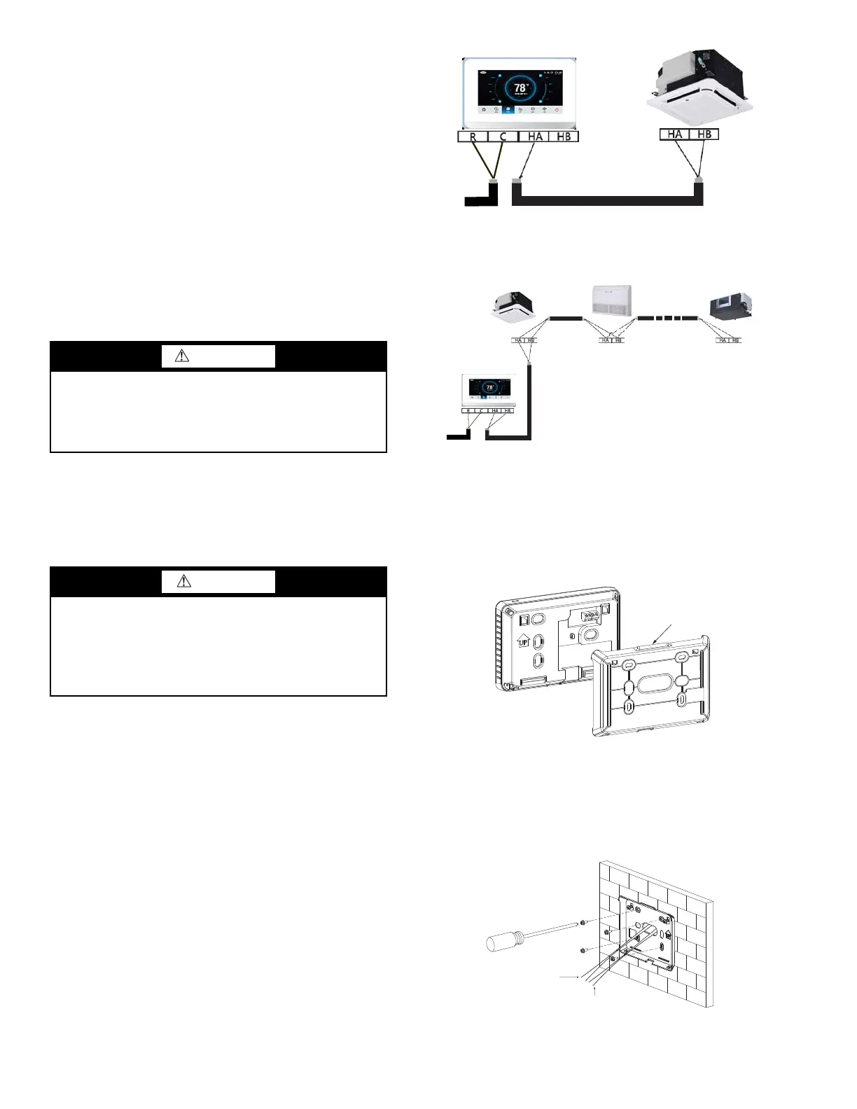
Wiring the controller —
1. Using 2-core shielded
twisted pair cable, 16 to 20 AWG
(American Wire Gage), attach the control cable to the
HA/HB terminal on the indoor unit and other end to the
controller HA/HB terminal. For connecting the controller
to a single indoor unit, see Fig. 3. For connecting the
controller to multiple indoor units see Fig. 4.
2. Connect field-provided 24VAC power to R and C
terminals.
1. Remove back cover from controller as shown in Figure 5.
2. Cut a hole in the wall for the 2 wire bundles. Run the
wires through the hole in the wall and through the center
hole in the back cover.
3. Screw the back cover to the wall as shown in Figure 6,
and attach the power and control wires to their respective
terminals.
WARNING
Electrical shock can cause personal injury and death.
Before installing thermostat, shut off all power to this
equipment during installation. There may be more than one
power disconnect. Tag all disconnect locations to alert
others not to restore power until work is completed.
CAUTION
Failure to follow this caution may result in equipment
damage or improper operation.
Improper wiring or installation may damage the
thermostat. Check to make sure wiring sequence is correct
at both ends before proceeding with installation or turning
on unit.
Fig. 5 — Remove back cover from controller
Fig. 6 — Attach back cover to wall
WALL
24 VAC
(eld-supplied)
Control Wire
24VAC
(eld-supplied)
Control wire
NOTE: Connect up to 16 indoor units.
NOTE: Ground cable shielding at each indoor unit.
Fig. 4 — Connecting to multiple indoor units
NOTE: All of the indoor units connected to the controller
must be on the same refrigerant circuit and connected to the
same outdoor unit.
Mounting the Controller —
24 VAC
(eld-supplied)
Stranded twisted pair shielded, 2-core copper wire
NOTE: Ground cable shielding at indoor unit
Fig. 3 — Connecting to one indoor unit
 Loading...