12
Step 3 — Mount the Unit
Mount the unit using the hanger bolts at the locations shown in
Fig. 2 and 3, top view. Use
3
/
8
-inch all-threaded rod. For unit
weight, see Table 2.
MOUNTING THE UNIT — Lift the unit on to the hanging
rods for mounting:
1. Use rods and fasteners to suspend the unit at the factory-
provided mounting holes.
2. Adjust the height of the unit until the bottom is level with
the false ceiling. There must be adequate space to provide
enough pitch for the drain.
3. Secure the unit in position with locknuts and washers on
both sides of the mounting bracket. Ensure that the
threaded rod does not protrude more than two inches
below the mounting brackets as shown in Fig. 14.
INSTALLING THE DUCT — Connect the return and supply
ducts to the duct collars provided on the unit. Adequate
distance between the return and supply diffusers should be
maintained to avoid short circulation of air within the space.
The filter is located on the return side of the unit, on the rear or
bottom depending on the return air inlet arrangement.
RETURN AIR ARRANGEMENT — Based on the return air
arrangement requirement in the field, the unit can be modified
from rear return to bottom return. Follow the instructions
below to change the return air arrangement.
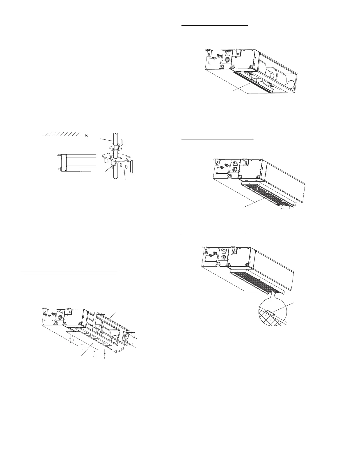
Remove Air Filter Frame and Cover Plate
1. Remove the screws that secure the filter frame to the rear
of the unit.
2. Remove the screws that secure the return air cover plate
to the bottom of the unit and set the cover plate aside. See
Fig. 15 below.
Fig. 15 —Removing Air Filter Frame and Cover
Plate
Apply Foam Insulating Tape
1. Apply foam insulating tape to the return air opening on
the bottom of the unit. See Fig. 16 below.
Fig. 16 —Applying Foam Insulation Tape
2. Use the existing screws to re-install the return air cover
plate on the rear of the unit.
Re-install Air Filter and Frame
— Re-install the return air
filter and the filter frame on the bottom of the unit. Refer to the
arrows in Fig. 17.
Fig. 17 —Re-installing Return Air Filter and Frame
Secure the Frame and Filter
— Use the provided clips to
secure the filter inside the filter frame. See Fig. 18 below.
Fig. 18 —Securing the Filter and Frame
Fig. 14 — Threaded Rod
INDOOR UNIT
LEVELING
NUT
” THREADED
ROD
MOUNTING
BRACKET
SUPPLY AIR
OPENING
FRONT VIEW
When the unit is
level, tighten
nut to secure
the position of
the mounting
bracket on the
threaded rod.
Side rail
Dentilation panel
RETURN AIR
RETURN AIR
FILTER FRAME
COVER PLATE

 Loading...