P Q
X Y
X Y
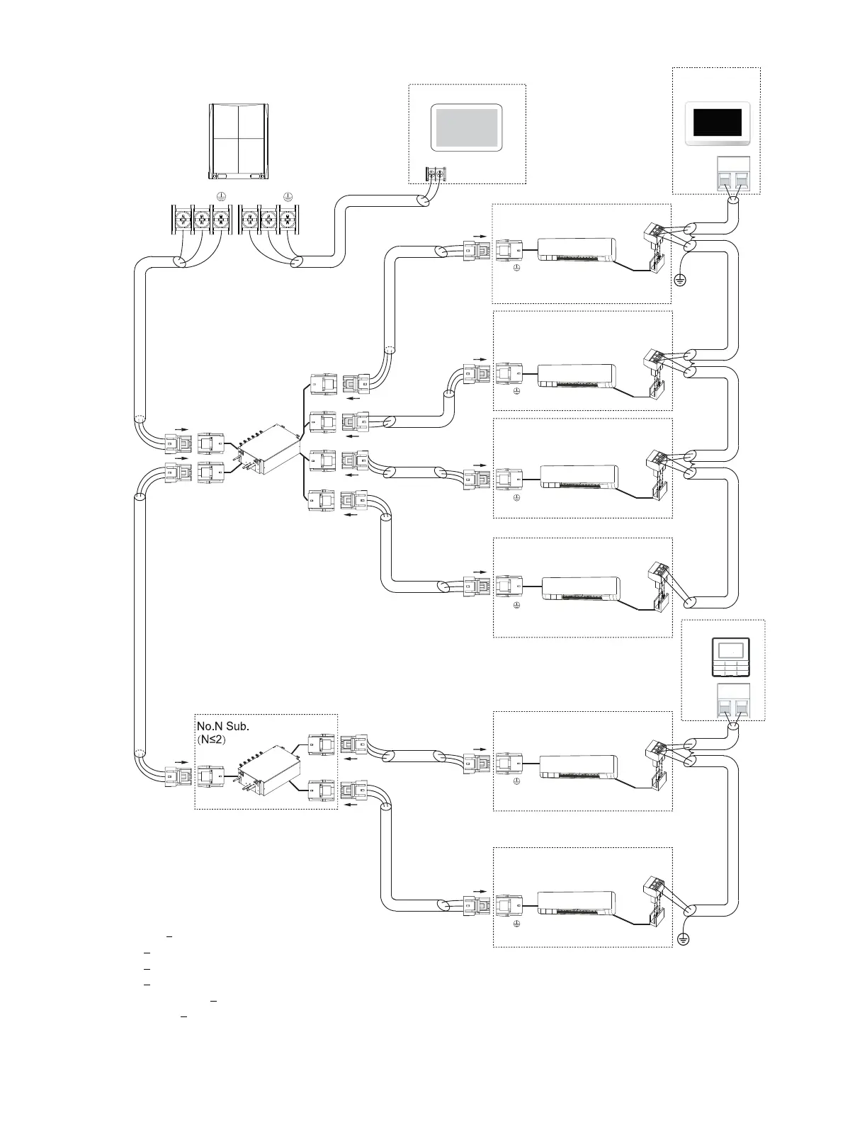
Main MDC
MDC
outdoor unit Centralized controller
HA HB
P Q
P Q
P Q
P Q
P Q
P Q
wired controller
HA HB
To No.1
indoor
To No.2
indoor
To No.3
indoor
To No.4
indoor
To No.1
indoor
To No.2
indoor
To outdoor
To Sub.MDC
To outdoor
Indoor unit 1#
L1
L2
L3
L3
L3
L3
L4
L4
L5
L6
L7
L8
L9
L10
L11
Indoor unit 2#
Indoor unit 3#
Indoor unit 4#
Indoor unit 5#
Indoor unit 6#
Touch screen
wired controller
Note: 24v DC Power
Note: Power from IDU
Maximum wiring length
L1+L2 < 3937 ft. 18 AWG, 2-Core Stranded Shield
L3 < 3937 ft. 18 AWG, 2-Core Stranded Shield
L4 < 3937 ft. 18 AWG, 2-Core Stranded Shield
L5 < 3937 ft. 18 AWG, 2-Core Stranded Shield
L6+L7+L8+L9 < 820 ft. 18 AWG, 2-Core Stranded Shield
L10+L11 < 820 ft. 18 AWG, 2-Core Stranded Shield
HA HB HA HB
HA HB
HA HB
HA HB
HA HB
Fig. 20 — Typical Communication Wiring of Heat Recovery System