12
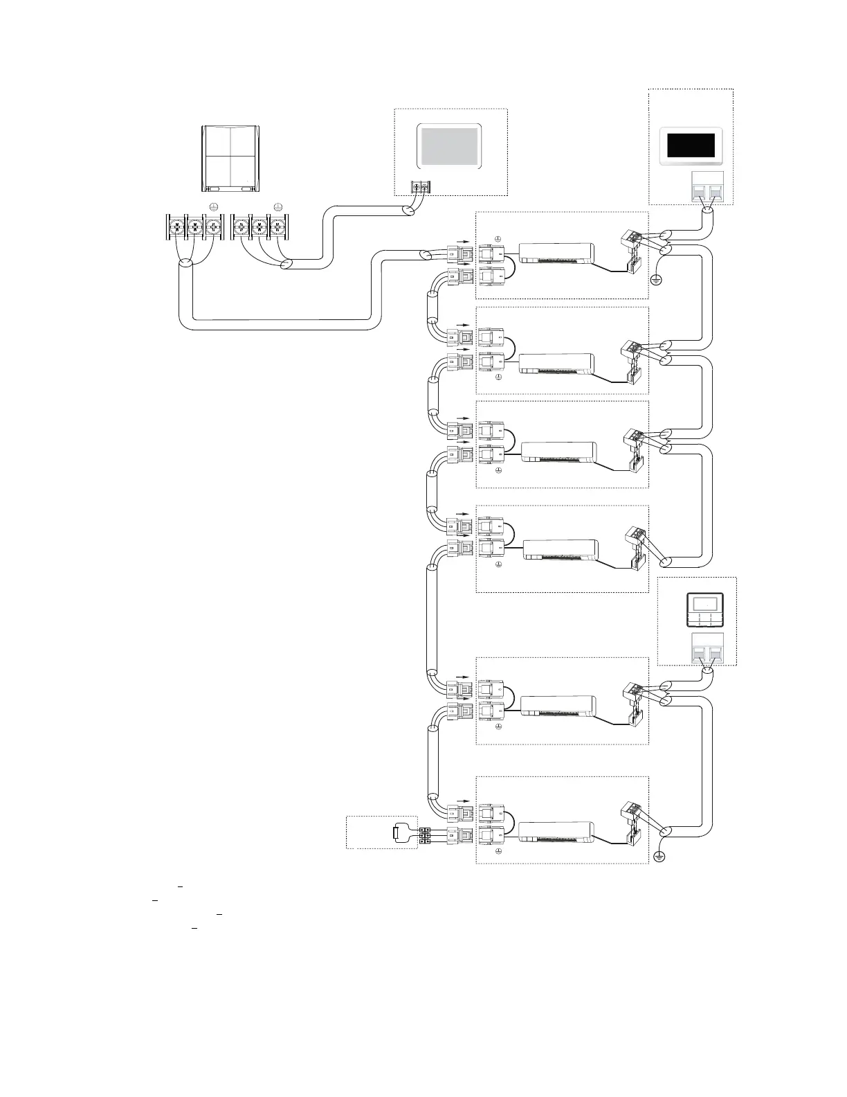
Fig. 21 —Typical Communication Wiring of Heat Pump System
P Q
X Y
X Y
Centralized controller
HA HB
P Q
P Q
P Q
P Q
P Q
P Q
wired controller
HA HB
L1
L3
L5
L6
L7
L8
L9
L10
L11
L3
L3
L3
L3
Outdoor unit
Indoor unit 5#
Indoor unit 6#
Indoor unit 3#
Indoor unit 4#
Indoor unit 2#
Indoor unit 1#
P
Q
Note: Power from IDU
Maximum wiring length
L1+L3 < 3937 ft. 18 AWG, 2-Core Stranded Shield
L5< 3937 ft. 18 AWG, 2-Core Stranded Shield
L6+L7+L8+L9< 820 ft. 18 AWG, 2-Core Stranded Shield
L10+L11 < 820 ft. 18 AWG, 2-Core Stranded Shield
Note: 24v DC Power
Touch screen
wired controller
HA HB
HA HB
HA HB
HA HB HA HB
HA HB
Network
Resistor
NOTE: Network resistor is shipped with the outdoor unit for
installation on heat pump systems.
LEGEND
AWG
—
America Wire Gage
IDU
—
Indoor Unit