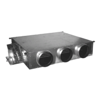
4.4.1 - Description
The Carrier unit is tted with G3 lter as standard (85%
gravimetrie lter) or G4 lter as option, according to
standard EN 779. Medium re rating M1, metal wire
frame.
Different lter access are available:
• Unit with non-ducted return air: Access is from the
rear of the unit.
• Unit with ducted return air: Access is from below.
4.4.2 - Air lter replacement
Air lters should be changed regularly. Filter life depends on
the rate at which the lter becomes clogged, which depends
upon the cleanliness of the working environment.
If clogged lters are not changed they can increase the air
pressure drop, trapped dust particles may be given off and
entrained in the air supply, and the general performance of
the unit may be degraded (as the air ow reduces).
NOTE: When installing a unit in a ceiling void, check
that no T-bars will obstruct lter access and removal.
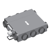
4.5.1 - Fresh air controller with constant air volume
The 42EM unit can be tted with a constant fresh air ow
controller, xed at 8.5 l/s (30 m
3
/h) or adjustable from 17 l/s
(60 m
3
/h) to 44 l/s (160 m
3
/h) to allow contol of the
introduction of fresh air and of the air change rate.
Controllers with adjustable fresh air ow:
The diameter of the spigot housing the fresh air ow
controller is 125 mm.
The fresh air controller may be modied on site by relocating
or removing two plastic restrictors in order to change the
maximum constant fresh air ow of 17 1/s (60 m
3
/h) to 44 1/s
(160 m
3
/h). A label on the 42EM shows how to adjust the
two plastic restrictors (Fig. 11).
Modication procedure
• Disconnect the fresh air duct from the spigot on the
unit.
• Remove or reposition the two plastic restrictors,
following the fresh air ow controller.
• Reconnect the fresh air duct to the spigot.
IMPORTANT: If the unit is tted with a return air
temperature sensor, the constant fresh air ow rate must
not exceed 50% of the supply air ow delivered by the
unit at minimum speed.
NOTE: To operate correctly, the 8.5 l/s (30 m
3
/h) the
constant fresh air ow controller requires a differential
pressure in the range of 50 Pa to 200 Pa. The controller with
adjustable fresh air ow from 17 l/s (60 m
3
/h) to 44 l/s
(160 m
3
/h) requires a differential pressure in the range of
70 to 200 Pa.
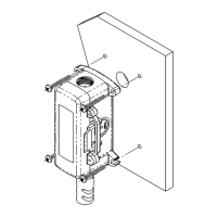
4.5.2 - Fresh air controller with variable air volume
The 42EM unit can be equipped with an optional variable
fresh air ow controller from 0 to 55 l/s (0 to 200 m
3
/h).
This is connected to the numeric Carrier controller and can
regulate the fresh air intake in two ways:
• Either using a xed rate set by the installer that can be
recongured as required
• Or based on the CO
2
level; in this case it is connected
to a CO
2
sensor via the Carrier numeric controller (the
CO
2
sensor is located opposite the fresh air inlet).
NOTE: With the variable fresh air ow controller the
upstream pressure in the fresh air duct must be 180 Pa.
These valves are either two-way or four-way type (three-
way with integral bypass). The body of the valve is designed
to withstand a 16 bar operating pressure.
With this option, the couple (valve + actuator) is usually
normally closed (NC).Thus, the water ow is null in case of
power cut. To ll the installation, to equalise the water
circuits and to purge the units, the actuators must be
connected to the power supply and the valves must be
opened via the controller (thermostats or BMS).
For the replacement of these components refer to the
chapter ‘‘4.6.3. - Actuator replacement procedure’’.
4.6.1 - 230 V - Actuators
Two types of valve actuators are provided : electrothermal
actuator (on/off control) or modulating actuator (3-point).
The actuator supply is 230 V a.c.
4.6.2. 24 V - Actuators
Three types of valve actuators are provided : one
electrothermal actuator (on/off control) or two modulating
actuators (3-point or 0-10V).
Both modulating actuators can be operated manually with a
hexagonal key. The 0-10V command voltage range of the
modulating actuator can also be adjusted.
The actuator supply is 24 V a.c.
NOTE: 24V actuators are not compatible with Carrier
controllers (Thermostats A/B/C/D, HDB & NTC).
4.6.3 - Actuator replacement procedure
The actuators on both the chilled water and the hot water
valves may be replaced if either develops a fault.
WARNING : Do not connect on the same neutral wire the
valve actuator 24 Vac and the controller.
 Loading...