• Disconnect the power supply to the unit before carrying
out any work on a unit.
• Disconnect the actuator power supply cable.
- 230 V type actuator used with the Carrier
numeric controller: Disconnect the actuator
power supply cable tted with a quick connector.
- 230 V actuator used with an electronic
thermostat: Remove the plastic protection cover
held in place with two screws. Disconnect the
actuator power supply cable connected to the
quick connector. This can be done by pressing
down the spring tongue using a screwdriver and
pulling out the wire from the appropriate terminal.
• Uncouple the faulty actuator. Retting is by the reversal
of the procedure described above.
WARNING: Ensure that the actuator is rmly screwed to
the valve body (maximum torque 15 N·m).
4.6.4 - Valve body replacement procedure
• Disconnect the power supply before carrying out any
work on a unit.
• Close the isolating valves on the manifolds.
• Unscrew the union nuts to disconnect the exible water
pipes.
• Remove the valve actuators taking care to identify the
cooling and heating valves.
• Disconnect the exible condensate drain pipe which is
held in place by a collar (the collar is not supplied by
Carrier).
• Remove the two-way or four-way water ow control
valve bodies. Depending how the unit is congured,
the four-way valve coupling may be tted with a
heating/cooling changeover switch, if so do not
remove it.
• Fit the new valve body to the coil (t new gaskets).
• Reconnect the exible condensate drain pipe which is
held in place by a collar (the collar is not supplied by
Carrier).
• Ret the valve actuators taking care to ensure that
they are correctly xed to the valve body.
• Reconnect the exible water pipes by tightening the
union nuts. Retighten all the water connections and
ensure that all gaskets have been changed and correctly
tted (maximum torque 15 N·m).
• Open the isolating valves on the manifolds and purge
all air from the system.
• Check that there are no leaks and reconnect the power
to the unit.
WARNING: When replacing a valve always ensure that
the direction of ow through the valve is as shown by the
arrow on the valve body. If the direction of ow is wrong,
the valve body will deteriorate rapidly.
Minimum bending radius:
• non-insulated pipes 72 mm
• insulated pipes 106 mm.
electric heater
WARNING: Disconnect the power supply before carrying
out any work on the unit.
If the electric heater develops a fault, it must be replaced;
this requires the removal of the fan motor assembly: Fig. 17
(17a = screw).
CAUTION: Do not touch the live metal heater elements
when the electric heater is connected to the power supply.
Electric heater replacement procedure:
• Remove the lter.
• Remove the fan motor assembly access panel.
• Identify and note the fan speeds wired to the auto-
transformer terminal block. Disconnect the power
supply cable.
• Remove the fan motor assembly.
NOTE: Be careful not to touch the fan blades during
the removal process to avoid unbalancing the fans.
• Disconnect the electric heater power supply cables
and remove them through the cable conduit.
• Unscrew the defective heater(s) and replace it (them).
• Replacement of the fan motor assembly is by the
reversal of the above procedure.
WARNING : Carrier Electronic thermostat type B and D
are embedded with Electric heater relay 8 Amps.
Accordingly, Carrier requires an additional protection
relay for electric heater 2000W and 3200W.
WARNING : In case of customer supplied controller,
Carrier recommends to set up an additional protection
relay corresponding to the electric heater capacity.
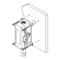
According to the g. 26, the condensate pump installation
require the following actions:
• Press the pump at the lowest position according to the
available height in the false celling (g. 26b)
• Check the sealing of the hydraulic connection of the
condensate pump and condensate recovery
The meaning of the electrical wires is described below:
• Brown - Blue wires : Electrical supply 230V 50/60Hz
• Black - Grey wires : Alarm contact Normally Closed
(NC) 250V/8A maxi
 Loading...