Do you have a question about the Carrier 42NQ009N and is the answer not in the manual?
| Model | 42NQ009N |
|---|---|
| Cooling Capacity | 9000 BTU/h |
| Refrigerant | R410A |
| Power Supply | 220-240V, 50Hz |
| Cooling Capacity (ton) | 0.75 ton |
| Outdoor Unit Noise Level | 50 dB |
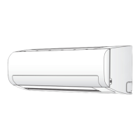
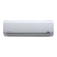
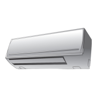
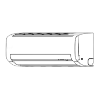
Diagrams and dimensions of the indoor unit components.
Diagrams and dimensions of the outdoor unit components.
List of electrical parts for the indoor unit with specifications.
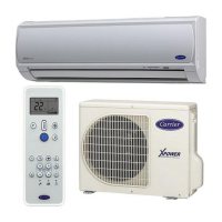
Details on remote control functions, buttons, and display indicators.
Describes the roles of indoor and outdoor unit controllers and fan control.
Details on Automatic, Cooling, Heating, Dry, and Fan only modes.
Controls compressor/fan to prevent excessive refrigerating cycle pressure.
Prevents indoor heat exchanger from freezing by controlling compressor/fan.
Operation to melt ice on the outdoor heat exchanger during heating.
Prevents input current from exceeding specified values by controlling outdoor fan.
Mode for faster cooling/heating by increasing fan speed and adjusting temp.
Energy saving mode that adjusts set temperature automatically.
Allows the unit to restart automatically after a power failure.
Important safety precautions for installation and handling of the unit.
Visual guide for the placement and connection of indoor and outdoor units.
Details on optional installation parts and outdoor unit fixing.
Installation procedures specific to the indoor unit.
Installation procedures specific to the outdoor unit.
Miscellaneous procedures like gas leak test and auto restart setting.
Step-by-step guide to diagnose and resolve issues.
Initial checks for power supply, connections, and operational status.
Basic diagnosis steps and interpretation of unit indicators.
Using the remote controller to retrieve error codes for self-diagnosis.
Flowcharts to guide troubleshooting for specific operational failures.
Diagnosing issues related to the remote control and indoor P.C. board.
Procedures for replacing parts of the indoor unit.
Procedures for replacing parts of the outdoor unit.
Exploded views and parts list for the indoor unit assembly.
Exploded views and parts list for the indoor unit components.
Exploded views and parts list for the outdoor unit.